Zeiss Ikon Contax Camera Repair
A home for your Zeiss Ikon Contax, Contarex or Super Ikonta camera!
Sections
- How Often is Servicing Required?
- Special Tools
- What Condition is Your Camera In Now?
- Contax Shutter Accuracy In The Camera Today
- Contax Shutter Accuracy When The Camera Was New
- Inherent Shutter Reliability Problems
- The Main Shutter Design Fault
- Shutter Disassembly Shutter Assembly
- Shutter Tapes
- Shutter Capping
- Shutter Cocking and Film Advance
- Clearing a Shutter Jam
- The Illustrated Camera
Overhauling A Contaflex 35mm TLR Camera
This article on the Contaflex TLR is dedicated to Mr. Moses Weitz. He is a true friend of Photography and the world's greatest collector of the Contaflex TLR. I shall always be grateful for his knowledge, kindness and generosity. He also had six TLR's restored here and I am sure this is a world record for any camera collector.

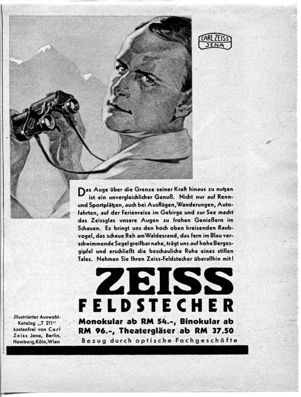
This may seem to be a strange picture to use in advertising announcing the Contaflex TLR. But there is a good historical reason for the sinister menacing appearance of the man holding the camera. At the time this brochure was printed Germany was being made over by the Nazis. Part of this program was propaganda to demonstrate what a pure "aryan Nazi" would look like. Because the concept of "aryan Nazi" as pronounced by the Nazis was stupid much that came out of it, including pictures of the ideal aryan Nazi appear stupid and very strange when viewed from our perspective in history. This illustration demonstrates the illustration artists in the Zeiss Ikon advertising department were not immune from being strongly influenced by the propaganda barage being unleashed on Germany at that time. The illustration is typical of a lot of advertisements of all kinds published in Germany during the early Nazi time in power.
Zeiss used this model in another advertisement for Zeiss Binoculars from 1932. If you'd like to see him in another pose just use this link:
1932 Zeiss Binocular Advertisement
A very rare copy of the Contaflex TLR Instruction book has been found and scanned. It is available for you to download for free. Itis a 7.0 Mb PDF file so it may take a little while to load but if you are interested in the Contaflex TLR and its lenses and accessories it's well worth the time. Just use the link below.
Contaflex TLR Instruction Book
How Often is a Servicing Required?
 The answer to this question depends on several factors. If you
intend to use your Contaflex TLR in regular service throughout the year,
it should be serviced at least every two years. If it will be used
regularly, but occasionally throughout the year, it should be serviced
at least every five years. If you want to keep it as a collectable,
it should be serviced once before being put on display. The lubricants
I use are modern synthetic oils and greases. They will not dry up
or deteriorate. A camera serviced as the one in this article has
been serviced will remain reliable for many years.
The answer to this question depends on several factors. If you
intend to use your Contaflex TLR in regular service throughout the year,
it should be serviced at least every two years. If it will be used
regularly, but occasionally throughout the year, it should be serviced
at least every five years. If you want to keep it as a collectable,
it should be serviced once before being put on display. The lubricants
I use are modern synthetic oils and greases. They will not dry up
or deteriorate. A camera serviced as the one in this article has
been serviced will remain reliable for many years.
Zeiss used whale oil based lubricants in the Contaflex TLR. The oils oxidize, dry and become hard. The greases become hard and form glue like deposits. It takes a lot of skill and labor to disassemble the entire camera, carefully clean each and every piece and screw, lubricate them properly, and assemble them back together correctly. The Contaflex is a very complex camera and there are very few people willing to work on them.
There are not a lot of Contaflex TLR's in the world today, perhaps only 2500 of the original 4500 ever manufactured. Most of these have been extensively worked on to keep them working or in the attempt to overcome original factory defects. When buying a camera made in the 1930's it's usually not a safe assumption to assume that the camera worked properly when it was made and that all it needs today is a little oil here and there to get it working right.
Contaflex TLR Variations
During the period of manufacture of the Contaflex TLR from 1932 to 1944 Zeiss changed the shutter mechanism design three times resulting in four distinctly different Contaflexes. The changes in design were all concerned with the shutter curtains and the shutter curtain release with the goal of increasing shutter curtain latching reliability and curtain longevity. I have not yet been able to see enough of these rare cameras to be able to relate them to serial numbers but have seen all of them and they are descried here for your use:
1. Original Model 1932 - This model has riveted aluminum slat shutter curtains identical to those used in the first model Contax I. The curtains are delicate and fragile.
2. First change - The shutter curtain material is changed to brass but the design and method of construction is identical to the original 1932 model.
3. Second change - The shutter curtain design is changed to be similar to that used in the Contax II and III camera models. It is also changed from a riveted construction to screwed construction as used in the II and III. The Contax I type shutter curtain release latch in the camera body was changed so that it will hold the shutter curtain by the same hook on the curtains as is used in the II and III models.
4. Last change - The curtain release mechanism in the body is changed from the Contax I type to be identical to that used in the Contax II and iII. This is the most reliable and secure method of curtain latching.
Pictures of these changes will be posted as camera bodies as time permits..
Special Tools?
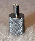
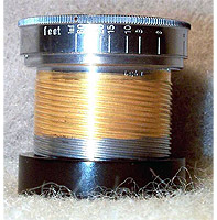
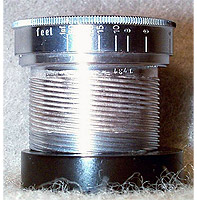
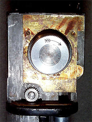
Anyone considering having their very rare and special Contaflex serviced will naturally have a concern for the work that is done which is not visible. It is important that the inside of the camera and all of its parts be in the same or better condition than they were before the camera was opened. This can only be realized when the camera is disassembled, aligned and finally reassembled using special tools that have been designed and made to do those specific jobs which require them to avoid damage. A good example of this is the holding nut of the shutter speed selector dial. It is shown in the next photograph:
Note how this is a slotted head nut, and the shaft rises above the head. It would be possible to force this nut with a screwdriver, but this would result in damage to one or both slots. The only answer is the manufacture of a special driver for use on this specific nut. The following picture is of the special wrench made to be used to loosen and tighten this particular nut:
Great care and craftsmanship goes into the making of all the special tools I make for each part of all the Contax cameras I service. It is my objective that your special Contax camera, no matter the model or its external cosmetic condition, shall be returned to you will all of the parts you do not see being in the same or better condition than they were when the camera was opened.
What Condition is Your Camera in Now?
It is very easy for a person who is somewhat handy with tools to clean up a Contaflex so that it makes a very fine exterior appearance. It is easy to clean the viewfinder focusing screen and the exterior leather and chrome. But unless it has been completely disassembled and serviced by a real expert in the past 5 years or so, it is a real mess inside.
The appreciation of the antique Zeiss Contax camera is a relatively modern phenomenon. Contax cameras made in the 1930's passed through the 1950's and 1960's when they were considered "un modern" and not given much respect. When people worked on these wonderful cameras back then, the object was to keep them working, and not to restore and preserve them. Another thing to consider is that lubricants, glues, leather treatments and preservatives were primitive in the 1950's and 1960's compared to those available to me today. When I restore a camera today a lot of the work I do is to undo the older work of others.
The Contaflex is different from the other Contax cameras. The reason for this is that the Contaflex is covered with a very thick leather, unlike the later models which are covered with a very thin leather. This thick leather traps moisture underneath it. The result, in many cases, is a severe mold and corrosion problem hidden underneath the leather. Zeiss used a shellac based adhesive to hold the leather on the camera. This adhesive has usually failed. Also, the leather has usually begun to deteriorate from the inner surfaces outward. This picture illustrates what was underneath the back leather of the camera shown above:
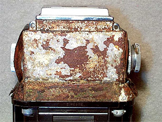
The yellow colored patches are mold growth, the white patches are corroded zinc, and the brown material is failed adhesive that is stuck to the camera. The most severe corrosion is in the strip just above the shutter curtains. This is a thin metal cover over the shutter mechanism. The problem of corrosion and failed adhesive complicates the servicing of this camera. I don't think anyone would want to let this condition remain uncorrected once it has been identified. But, removal of the leather without damaging it, treatment of the leather to preserve it, removal of the old adhesive, mold and corrosion and treatment to protect against future corrosion, completed by recovering of the camera with the original leather, is a tremendous amount of work. However, the value of a camera, not to mention the quality of the photographic experience with it, is greatly enhanced by being completely restored.
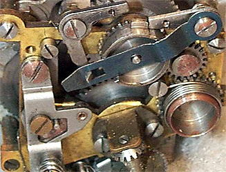
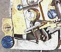
Zeiss made many of the shutter control components out of mild steel. Over the years the lubricant has dried leaving the steel open to corrosion due to time and moisture. Here is a close-up picture of a portion of the shutter control mechanism. Note how rust has already started to bite into the delicately machined parts and how the steel parts are dulled. It will take a lot of cleaning and hand polishing to make this mechanism function as smoothly and reliably as it did when it was new.
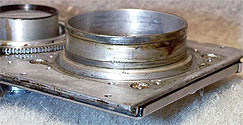
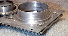
The next two pictures illustrate the condition of the grease in the innermost workings of the camera. These pictures are of the inner annulus of the taking lens focusing tube. This is inside the back side of the front plate of the camera. These pictures clearly show that even though this camera was "serviced" several times over its lifetime, no one bothered to go this deep into the camera.
The picture on the left shows the condition immediately after the lens mount was removed. And the right shows it after it has been cleaned. You can see an area of excessive wear in the center of the top of the left picture. The grease had lost its oil, and only the wax component was left. The result was excessive wear which is the black deposits of finely divided oxidized metal particles.
There are no spare parts available for the Contaflex. Each and every part in your camera is virtually irreplaceable. If your camera has not recently been completely disassembled, cleaned and lubricated it is very dirty with many parts grinding against each other dry. There are particles of old film and metal meshing with the gears, and accelerating the wear. Think of what your car engine would be like today if it was 66 years old and you had driven it continuously since it was new, without adding any oil or having the original old oil changed. This is what the inside of your camera is like now.
The Viewfinder Mirror:
Like any other TLR camera the Contaflex has a front surface reflecting mirror in the viewfinder. With the reflecting surface being made of bare pure silver over the years it can become corroded by the action of time, storage conditions and atmospheric contaminants. Just like everything else in this camera, Zeiss made the mirror to be made of optical glass of a specific and unusual thickness. About 20 years ago, one day when I was in my favorite (now sadly closed) camera store, the owner asked me if I would accept the present of a square of front surface mirror. Being highly reluctant to turn down anything remotely photographic and free I accepted the gift and promptly put it away. The other day, being presented with the necessity of obtaining a replacement mirror for a Contaflex, and faced with the difficult and time consuming process of silvering the old one, I decided to find and check out that long ago gift. It turns out to be an original piece of Zeiss Contaflex TLR Repair part and so I promptly cut a new mirror out if it. Here's a picture of the camera with the new mirror installed. Please note that a photograph of a perfect mirror will show the mirror being black:
If you have a Contaflex TLR that needs a new mirror please send me an email using this link:
The Lenses:
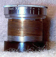
Here is the damage old lubricant does to the interior surfaces of the lens mechanism. These three pictures show the lens helical threads from the same 50mm f1.5 Contaflex Sonnar. The left picture shows the helicals after hand solvent cleaning. You can clearly see that the old grease has oxidized, hardened and formed a hard coat of varnish on the threads. The center picture shows the helicals after ultrasonic cleaning. On this Lens Zeiss plated chrome over the threads after they were cut. You can see that over the years the old grease became acid as it oxidized and has dissolved away all of the original chrome plating. The right picture shows the results after the threads are restored by Rhodium plating. Rhodium is a self lubricating precious metal that is impervious to acid. It is less hard than chrome, but will last for many years. The only way to restore the original focusing "feel" to this camera was to re plate the focusing threads. This is a difficult and expensive thing to do. But a Contaflex is worth the trouble.
The Light meter
The Contaflex TLR is the first camera to have a built-in light meter. Back in 1932 this was the level of rocket science and it stretched the envelope of all the available technology of the time. The meter itself is extremely large and heavy. The weight is a consequence of the very low voltage of the photocells available at the time. The lower cell voltage necessitated a large magnet in the meter. Back in 1932 magnets were also primitive and so a powerful magnet was a heavy one. In the following picture you can see the meter mounted on the back of the camera front plate:
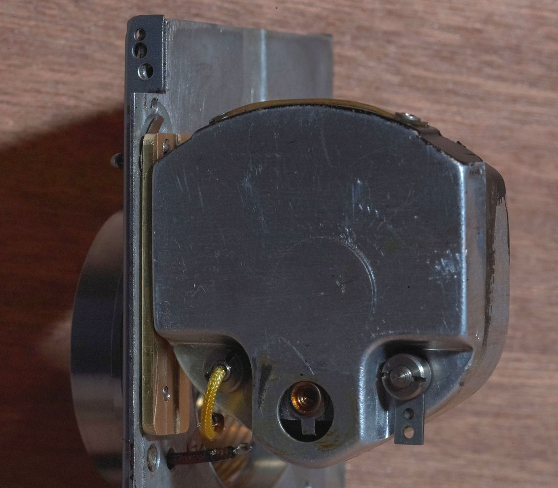
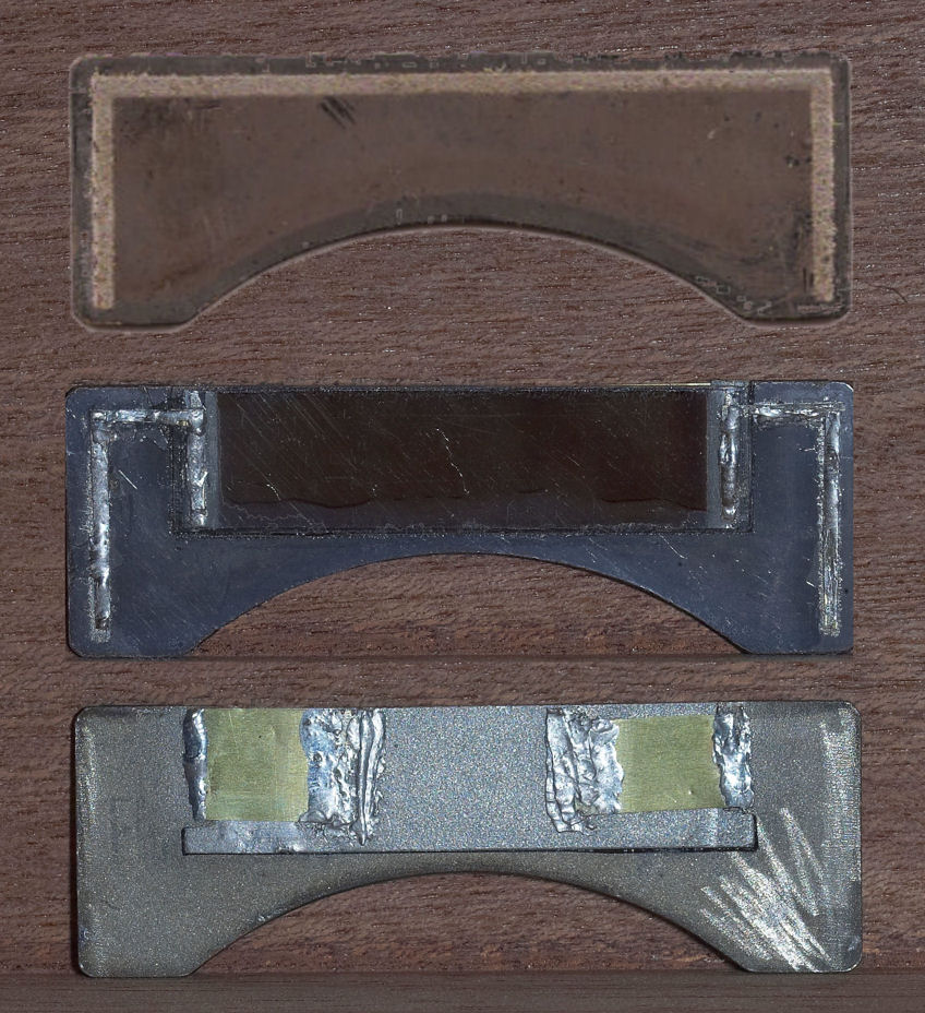
The consequence of such a large and heavy meter is that the mount has to be flexible and strong. The problem is there is a very tight space between the back of the meter and the back of the camera interior and so the mount can only be so thick and it is not possible to make it thicker to make it stronger. There is also the problem of weight. The TLR is very heavy and so Zeiss did everything possible to shave weight wherever possible and this included the meter mount. This is a picture of the front and back of an original Zeiss made TLR meter mount.

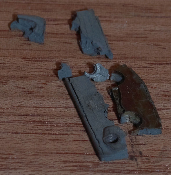
The problem with this mount is that it is made of a very height tech. alloy of magnesium that becomes very brittle with time. The result of this increasing brittleness is that the mount tends to shatter even if the camera is only put down hard. In three of the past four TLR's I've seen the meter mount has either been broken or shattered. This is a picture of a shattered meter mount:
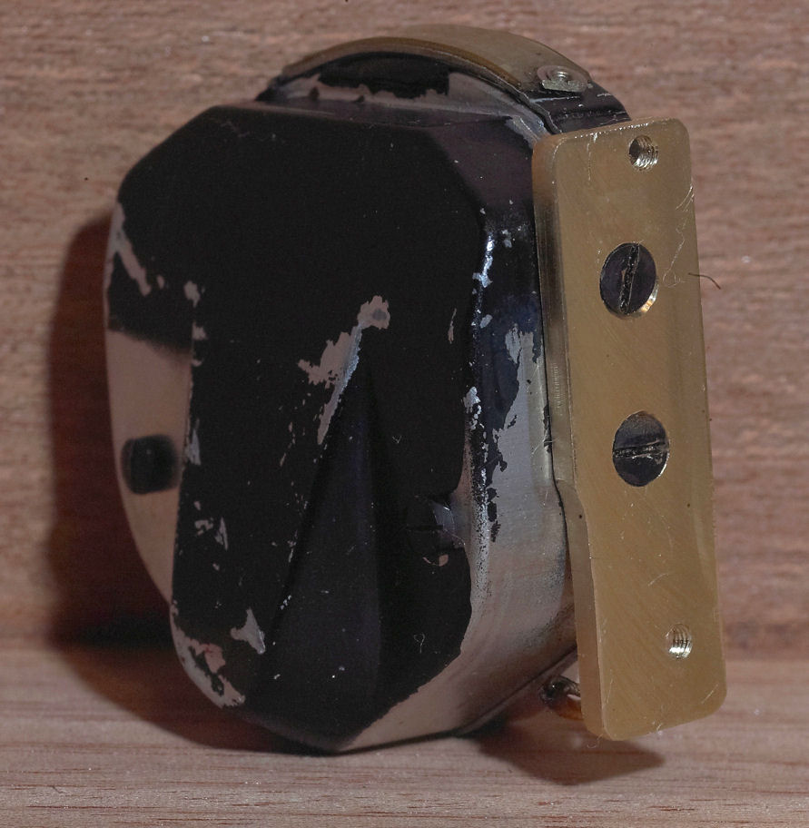
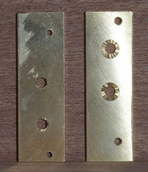
The only way to mount a meter properly today is to fabricate a new mount out of brass. Even though brass is a little bit heavier than the magnesium mount, it won't age nor will it become brittle with time. This is a picture of the back side of the meter (showing how large the magnet is) along with a new brass mount attached. You can see that the slot machined into the mount is not straight but has to be placed at a precision angle which varies slightly from camera to camera.
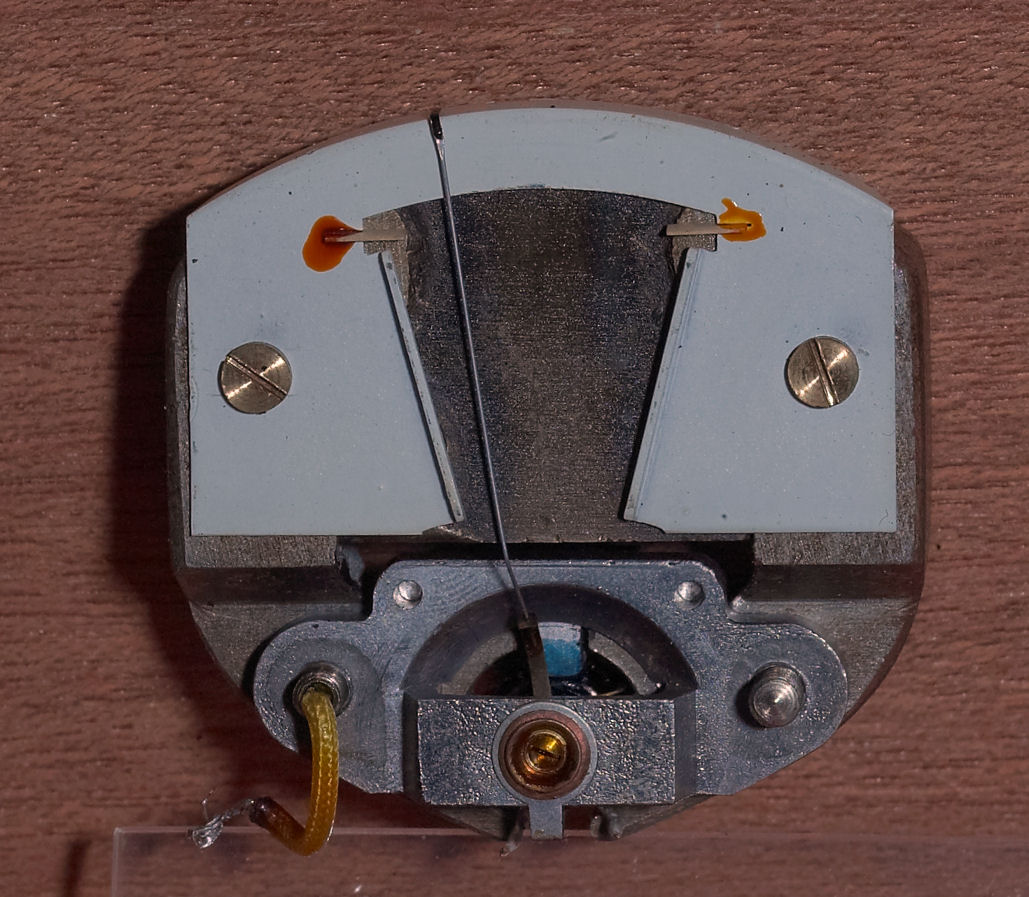
Here is a picture of the meter with the case removed showing the needle. The needle on this meter is extremely long and this makes it very sensitive to camera motion. It's important to hold the camera upright and steady when taking a light meter reading. You can also see that the clearances between the needle and the rest of the meter are very close. This makes it very easy for the needle to become bent and get stuck if the camera is bumped with too much force.
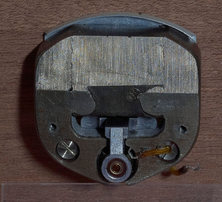
This is a picture of the back of the meter with the case removed. Most of the meter is a sold iron magnet.
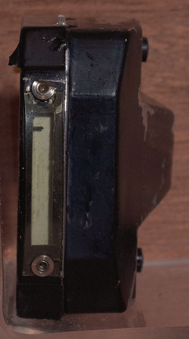
This is a picture of the face of the meter showing the top of the needle. This meter was made in 1932 and the plastic cover over the face is a little artifact of extreme high tech. in 1932. It's also interesting to note that this is the same plastic Zeiss used to cover the aperture indicator of the Contarex Bullseye. Look also at the connecting wire. It is a modern wire covered in flexible clear plastic that is smooth, clear and flexible today. These two little bits of plastic from the future demonstrate that every Zeiss product contains hidden within it proprietary high tech. artifacts which are easily 50 years ahead of everyone else:
This is a picture of some spare brass meter mounting blanks. The problem with making these mounts is that it isn't possible to make a standard mount that will fit every TLR. Each TLR camera is different and so the mount must be customized to fit the camera. This is necessary to make sure that the meter face hangs straight and is aligned so that the meter face is positioned exactly beneath the viewing window. This is a picture of the back and front of a blank mount to be used to modify to fit a particular camera. It takes about a day of work to modify one of these blanks to precisely fit an individual camera.
The meter senses voltage produced by light striking a selenium photocell. Back in 1932 the photocells were much more primitive than those available today. Unfortunately the selenium photocells available today come from only one source and this source will not manufacture replacement TLR cells. In order to restore the reliability and accuracy of the meter it is necessary to modify the old cell to accept a new cell. The following picture shows on the top an original new cell before it is cleaned,followed by the front of the cell after a new modern cell has been inset into it and the back side of the same cell:
You can see that the old cell has a precision recess machined into it to accept the new cell and that this new cell is carefully soldered into place to provide both structural rigidity and solid and long lasting electrical connections. Both normal solder along with special extremely low temperature solder is required. The new cell is the same as is used in the Contax IIIa camera light meter. Improvements made in selenium cell technology since 1932 provide that the new smaller cell is actually more powerful and more sensitive to light than the entire old cell and so the overall result of the cell transplant is an improvement in meter performance.
But it is also extremely important to clean every electrical component in the light meter system. The reason for this is that the oil and grease in the camera moves to cover every surface over time. As the camera is used the oil picks up microscopic particles of metal and becomes electrically conductive. Over time the light meter system becomes "shorted out" due to everything becoming covered with a thin film of conductive oil. The problem is that in order to access the light meter resistor strip to clean it the front plate of the camera has to be completely disassembled and this is a very time consuming and difficult job.. This is a picture of the front plate with everything removed.
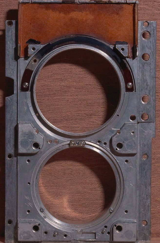
Surrounding the top of the upper lens hole you can see the curved resistor strip. This strip is made of plastic which has then been plated with a thick coat of silver which is then coated with a layer of carbon having varying thickness. Here is a closer view of it:
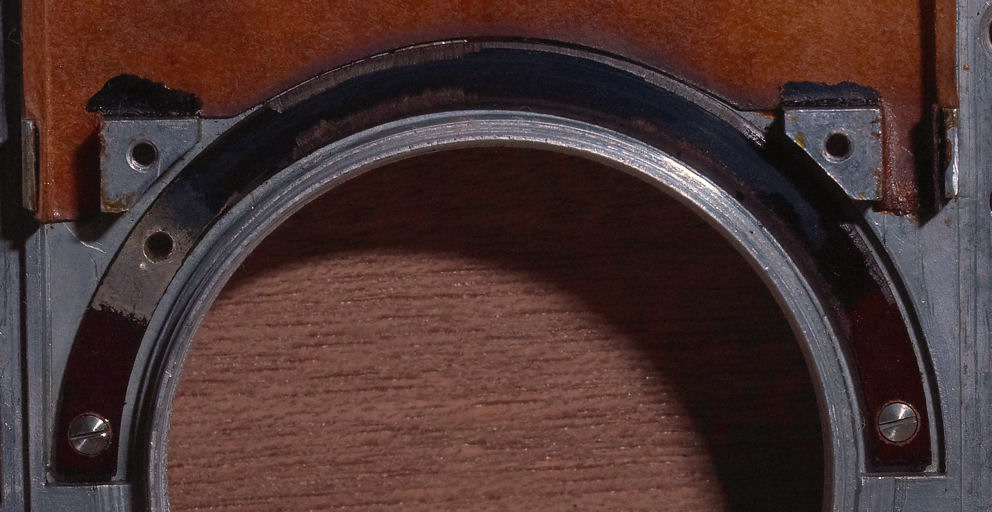
A rotating collar contains a carbon brush that contacts the surface of this resistor. As the meter control is moved, the carbon brush moves across the surface of the resistor and more or less electricity is conducted from the photocell to the light meter. Here's a picture of the resistor strip with the rotating brush installed over it:
Finally with this picture you can see how the photocell fits into the assembly:
Contax Shutter Accuracy Then:
The main fascination about the Contaflex camera is the shape of the body and the high shutter speed. It is stunning to consider that this camera had such a high speed back when there were no films that could support it. The Contaflex shutter is capable of 1/1000 of a second, but only when it is in perfect condition. Unfortunately, even when it was being made back in 1932, it was not being manufactured in perfect condition. Now, some 66 years later, the shutter is in horrible condition. The reason for this is that the Contaflex camera is not maintenance friendly. With perhaps the exception of the Contax I it is the most maintenance unfriendly camera ever made. All of the parts interlock each other so that it is not possible to gain access to critical shutter components, such as the escapement platform, without complete camera disassembly. It is for these reasons that most, if not all, Contaflex TLR cameras existing today have not been thoroughly serviced since the day they were made.
Inherent Shutter Reliability Problems
Even when it was new the Contaflex TLR shutter had reliability problems due to its design. It is important to consider that the Contaflex TLR shutter is the first in a long line of development of the top to bottom metal curtain shutter. Zeiss made many changes in the shutter design between 1932 and 1938, and most of these were to correct problems that are encountered in the Contaflex design which were also carried over into the Contax I. There are two inherent reliability problems with capping and shutter release.
Capping: The Contaflex shutter capping action is that the upper and lower curtains do not mechanically lock to each other as they do in the Contax I, II and III shutters. A bias between the upper and lower shutter curtain springs holds the curtains together while they are lifted when the camera is wound. The amount of this bias is decreased at the lower shutter speeds as the camera is wound. Occasionally, the curtains will separate when the camera is wound. The way to ensure this will not happen is to wind the camera with the shutter set at 1/1000 and then set it to 1/2 or B once it is fully wound. This problem is far less likely at shutter speeds of 1/150 and above.
Release: The Contaflex and the Contax I share the same shutter release design. Catches on the lower shutter curtain engage into slots located at the right and left in a thin metal strip at the top of the shutter cavity. When the shutter release is depressed, this strip is lifted to disengage the catches, allowing the shutter curtains to be pulled down by their respective springs. The catches are made of brass and the strip is made of steel. Over time the tiny brass catch has a flat spot worn in its edge where it engages the slot in the steel plate. Occasionally, this tiny flat spot will hold one side or other of the lower shutter curtain from releasing when the steel plate is lifted as the shutter release is depressed. The cure for this is to simply wind the camera to the next exposure and try again. In my experience, in all cases, the shutter will release on the second try. It is not advisable to attempt to correct this problem by filing the catch because the catch is very small, and it would be easy to go too far resulting in the need for a very difficult, time consuming, expensive and unnecessary repair. It is better to live with this problem.
There are no cures for these problems. The main point to keep in mind is that the shutter in this camera is the first attempt by Zeiss to invent a new kind of 35mm camera shutter back in the days when 35mm cameras were being first invented. The first of anything always has room for improvement. Living with the good and bad points of this camera is part of the adventure of collecting and using these rare and special cameras.
Contax Shutter Accuracy Today:
The Contax shutters we have today have traveled through at least 66 or more years of time. In this time all of the steel and brass shutter components have become oxidized and are covered by a very tenacious high friction oxidation layer. In addition, the lubricants used in the shutter were both petroleum and marine animal based. In the past 66 or so years these lubricants have degraded and oxidized.
The lubricants used in the range finder mechanism were petroleum based. Petroleum based lubricants have a unique property. Over time they spread to cover all accessible surfaces. Take a drop of oil, put it in the middle of a three foot square steel plate, put it in a safe place, come back in a year and that drop will have spread to form a thin film over the top, back and sides of the plate.
Marine animal based lubricants dry up and harden. These are the natural processes that work to degrade a Contax shutter over the years.
In addition, all the original petroleum based grease has completely disintegrated into sticky muck and oil. The muck makes controls difficult to operate, and the oil saturates into places where the mechanism should run dry.
The Contax shutter is a mystery to many people and is perplexing for one reason. This is the fact the shutter spring is wound to a higher tension for the low speeds than for the high speeds. There is a seeming contradiction in this.
Normally the higher spring tension is for the higher speeds. This is the trick of the Contax shutter.
The answer is simple. The higher speeds are entirely friction dependent. The low speeds are obtained by the use of two escapements retarding the shutter movement by eating up the spring energy. Friction is good. The medium speeds use a single escapement. Friction is okay. The high speeds use no escapement, but rely upon variable shutter slit width, and the absence of friction. Accurate high shutter speeds cannot be obtained by adjustment of the initial shutter spring tension.
Accurate high shutter speeds depend upon two things:
- 1) Accurate adjustment of the 1/1000 shutter slit width and
- 2) The elimination of friction in the shutter mechanism to the maximum extent possible.
This is why people do not notice that a bound up shutter is actually bound up. However, when the high shutter speeds are selected, film will be grossly overexposed.
Taking The Shutter Apart:
The Contaflex camera must be completely disassembled in order for the shutter to be completely serviced. The Contaflex has many more parts than the later I, II and III models. These parts are all set into the camera body individually unlike the II and III models which are made of modular assemblies that can be removed separately. The best way to put it is that the Contaflex is more like a Chinese Puzzle Box than anything else. Among cameras it is unique. The peculiar complexity of its construction makes it very hard and exacting work to disassemble the Contax shutter. In the later Contax II and III models, tolerances were adjusted by the use of many very thin washers. The Contaflex contains very few washers to shim parts because the parts were made to great precision, are very delicate and must be handled with the greatest of care. Age and time have also caused parts to fuse, making it very difficult to separate them. Overall, the disassembly of the Contaflex requires great skill, patience, and understanding.
Shutter Assembly:
The Contaflex shutter has only one adjustment and this is the resting spring tension in the lower shutter curtain roller. When the shutter is assembled all of the gears must be carefully synchronized. If the assembly is as much as one tooth off in one direction, the shutter will jam when wound to the slowest speed. If it is just one tooth off in the other direction, the proper slit width for 1/1000 cannot be obtained. There are many other things to keep in mind while disassembling and reassembling the Contax shutter. The proper choice of lubricants is also essential. Some bearings require oil and others require grease. Some run dry. I use the most modern synthetic Swiss and French clock and watch lubricants in the Contax shutters I rebuild. These lubricants are more or less permanent. They do not degrade, harden or migrate.
Shutter Tapes:
The original shutter tapes were made to explicit design criteria for Zeiss. When they were made the Contaflex the original shutter tapes were made of cotton. Cotton is not durable in this service, but Zeiss did not change to the use of silk tapes in the later Contax I cameras. Most Contaflex cameras today have either silk or nylon tapes in them. Nylon tapes were used in the post war IIa and IIIa models. If the shutter tapes were replaced before the war, silk was generally used. If after the war, then nylon was used. In either case the problem is that these tapes have become clogged with oil that has migrated out of the decayed grease and do not allow the curtains to move with the required velocity to produce the set speeds.
The tapes used during a modern rebuild are the silk tapes. They have a specific weave and dimensions. These are not generally available today. Substitute material is used by many people. Many people use nylon, rayon or satin ribbon obtained from craft supply houses. There are three problems with this tape. The size is usually incorrect, the material stretches under tension, and it is not durable. Only silk provides the required durability and resistance to stretching under tension.
Only the required dimensions result in the proper friction when the tape slides through its slots in the upper shutter curtain. I use new silk shutter tapes made to the same specifications as the original.
I am sorry to have to say I cannot sell any. The supply is sufficient only for my needs. The following picture is of a special tool used to set the shutter tape length:

This fixture ensures that the shutter curtain edges will be absolutely parallel during exposure. It also demonstrates that to repair Contax cameras, one must be able to afford, or to make all of the special tools required to ensure the job is done right the first time. Tool design is a separate specialty. The making of tools requires some time since none of the original Zeiss tools are available to copy.
Shutter Capping:
The term "capping" refers to the action of the shutter curtains when they mate and lock together at the end of the exposure. This term does not apply to the Contaflex since its shutter curtains do not lock together. The curtains are held together due to a built in bias between the springs for the lower and upper shutter curtains. This bias is strongest at the higher speeds. This explains why the shutter curtains occasionally separate during camera winding when the shutter is set at slow speeds.
The Contaflex shutter curtains are unique. They are different from every other model of Contax camera. Replacement curtains are not available.
There is a significant weakness in the Contaflex shutter. Two very thin metal fingers set into the lower shutter curtain slot, one on each side, that the upper curtain lip fits into when the shutter is closed. These fingers hold the upper shutter curtain lip from going into the slot too deeply and becoming wedged in tightly. They also hold the alignment of the upper shutter curtain.
If the the shutter spring tension is too high the force of the descending upper shutter curtain can hammer one or both of these fingers straight. If one finger is bent, the result is that the upper shutter curtain will have one side slightly higher then the other when the shutter is closed. If both are bent there will be a point of increasing tension when the shutter is wound. There may also be a slight click or popping sound when the shutter curtains separate.
The shutter must not be operated with this damage. Permanent and irreparable damage may be the result.
Never ever interfere with the operation of the shutter or attempt to correct a problem by manipulating the curtains from the outside. These things are likely to cause permanent and irreparable damage.
Shutter Cocking and Film Advance:
The winding knob also moves the film advance mechanism. The shutter mechanism located directly below the winding knob is extremely complicated. There is a shaft to which the knob is attached. This shaft actuates the film advance mechanism. There is a tapered steel pin attached to the underside of the winding knob. This pin mates with the shutter speed selector barrel. Rotation of this barrel cocks the shutter. Lifting up the winding knob allows the pin to fit into a series of slots in the top of the barrel. The slot selected controls the amount of rotation of the shutter mechanism and the spring tension. It is possible, with some effort, to shear off this tapered pin in an attempt to clear the shutter of a jam. Never ever force this knob. It is an expensive job to replace this pin. In addition, it is possible to completely ruin the shutter by warping of delicate components.
Clearing a Camera Jam:
Never ever force the winding knob. If the camera is jammed it must be opened to clear the jam. The camera cannot be un jammed by shaking or hitting it. The reasons why this is so are explained elsewhere in this document.
The Illustrated Camera:
I have put this page together to demonstrate the various steps in the complete overhaul service of a Contaflex 35 mm camera. The following pictures illustrate parts of the assembly process and pictures of critical cleaning and polishing steps. I am hopeful this first offering will help you understand the workings of this very unusual, complex and high precision mechanical marvel.
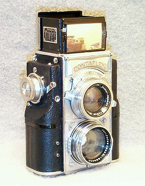
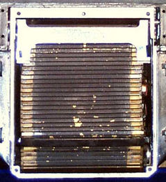
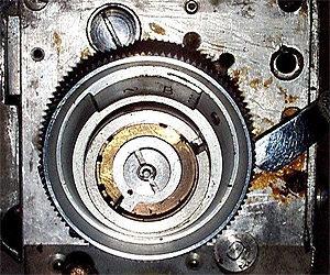
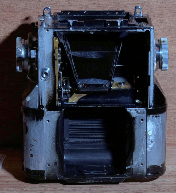
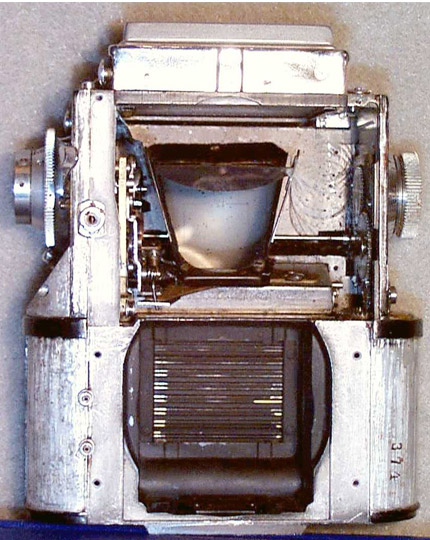
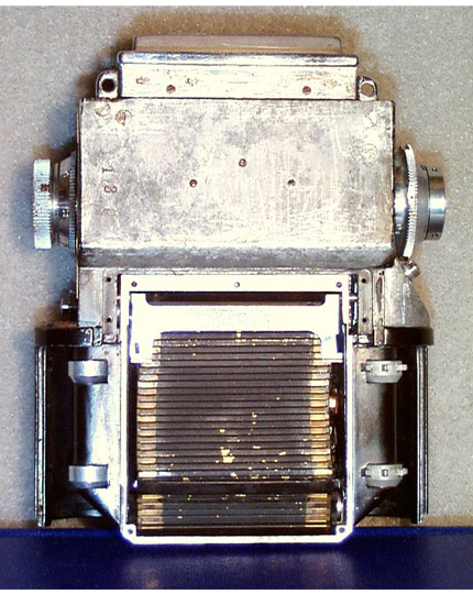
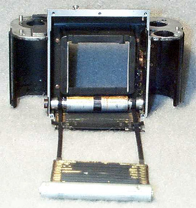
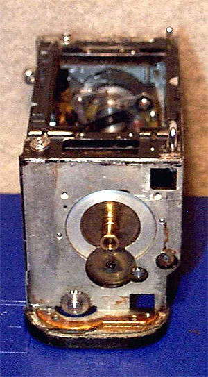
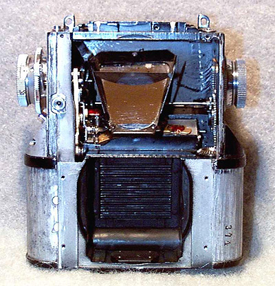
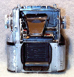
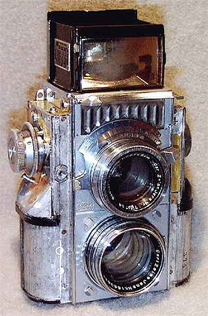
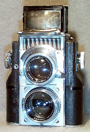
The first set of pictures is of the camera shell, still containing all of its internal mechanisms, after the front and back plates have been removed. The first picture is of the front of the camera showing the viewfinder mirror in the upper camera half, and the lens box and shutter curtains in the lower half.
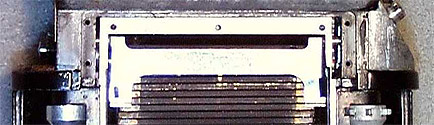
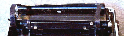
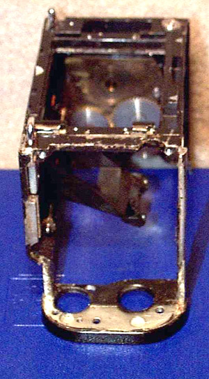
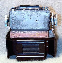
This picture shows the rear view. You can clearly see the shutter curtains. The Contaflex upper shutter curtain is very long and is much longer than the upper shutter curtain in any of the other Contax models. The slotted bar at the top of the shutter cavity is the shutter release. It is lifted up to release catches on the edges of the shutter curtain, allowing the shutter curtains to descend. The shutter is shown in the released position.
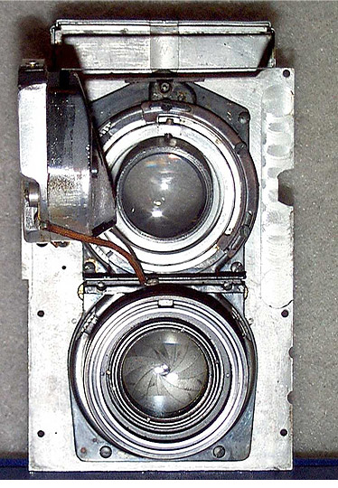
The next picture set is of the camera front plate. The first view is of the back. Both lenses are installed. The light meter is at the left, and the moving viewfinder parallax frame is visible at top.
This is a side view of the front plate. The light meter is visible as is the moving viewfinder parallax frame. It is interesting to note that Zeiss used a very uncommon clear plastic to cover the curved top of the light meter. You can see the aluminum rivets which were used to fasten it in place.

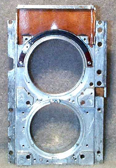
Finally, here is the front plate with everything but the variable resistor for the light meter and the back insulator for the light cell removed. It has been completely cleaned and is ready for reassembly.
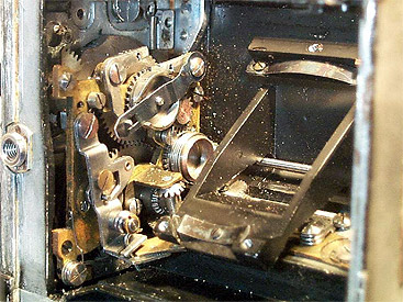
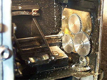
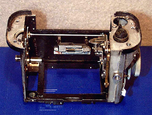
The next picture is of the shutter escapement and synchronizing mechanisms. This is an oblique view through the camera front to the left side. Note how tightly packed the miniature parts are. You can also see that the shutter escapement fits underneath the mirror support. It is interesting that the mirror support is cast with the body. Machining this was a very costly and complex operation indeed. Note how the brass is discolored and the body is full of dirt particles.
This picture is of the camera wall on the other side. It shows the complex rewind gearing and the gear to the film frame counter. Just to the right of the mirror mount is the pivot point of the shutter escapement. Note the shaft coming from the shutter works to the film frame counter gears.
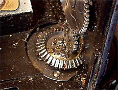
This next picture is a top view of the lower bevel gear. You can clearly see the mass of separated grease mixed with dirt and film chips. This is the typical state of all the lubricant in this camera.
This picture is a close-up of the left side of the camera exterior showing the film rewind knob and frame counter. Please note just below the knob is a gear. This is the gear that mates with the bevel gear above and completes the connection from the rewind knob to the film sprockets. This gear is covered with a bakelite plastic piece that makes this side of the camera have the same shape as the other.
The Contaflex camera body is made up of two main castings. In the following two pictures the top casting (right) is shown upside down so you can see more clearly how the mechanical components mate to each other.
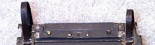
Here is a photograph of the lower casting with the shutter curtain in the process of being removed. The upper shutter curtain and roller have been taken out and stretched from the camera body. Note that the shutter tapes are black. Sometime back in the 1950's, the original cotton shutter tapes were replaced with the only Zeiss tape available, and this is the black nylon tape used in the IIa and IIIa cameras. This tape is too thick and was unsatisfactory. In an attempt to boost the low shutter speeds use of this thick tape causes, the tension on the lower curtain springs was increased beyond the normal setting. This had the result of bending the stop tabs in the lower shutter curtain slot, causing the upper curtain to be cocked when closed.
Here is a set of two pictures of the slot in the lower shutter curtain. In the first picture you can see two things. The first is that the shutter tapes are not the same length. This is the reason the stop tab on the right was more damaged than the one of the left. The tabs are folded down at the end of the fingers coming up, right and left, from the strip spring that is riveted in the center just below the slot. The two brass catches, which are right and left on the lower portion of the strip spring are used to hold the lower shutter curtain up when the shutter is cocked. The tabs are more visible in the second picture. You can see how the delicate spring on the left side has been distorted due to the unequal force exerted by the closing upper shutter curtain due to the unequal length shutter tapes.
This is a face on view down the slot. You can see the tab on the right is in better condition than the one on the left. This is because it has already been straightened as part of the repairs to this camera. The left tab is still dented from the excessive pressure caused by the over tightening of the upper shutter curtain spring as discussed previously.
This is a picture of the shutter unrolled out of the back of the lower casing. The upper shutter curtain is shown forward. You can see that the shutter tapes are of unequal length.
Next is a photograph of the right side of the camera with the rewind knob and film frame counter removed.
Next is a picture of the other side of the same casting with the shutter mechanism removed:
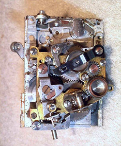
Here is a picture of the film advance and shutter control mechanism module from both sides.. Please note the rust on many of the steel components. The area between the top of the assembly and the top of the brass frame originally held the self timer for this camera. When it was received by me the self timer was missing. Disassembly of the camera reveals it was probably taken out by an amateur in an attempt to remove the shutter mechanism from the casting without first removing the film advance sprocket, which requires special tools. Removal of the self timer in this manner would subject it to irreparable damage. Thankfully, who ever made this attempt had learned enough from this damaging experience to close the camera back up as it was.

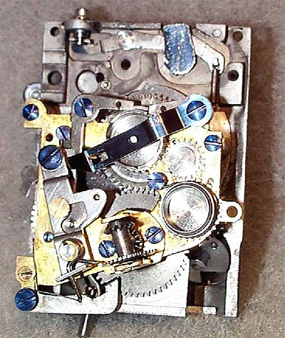
Here is a photograph of the same mechanism after it has been disassembled, cleaned, lubricated, and assembled. The steel screws have been blued to protect them from rust in the future.
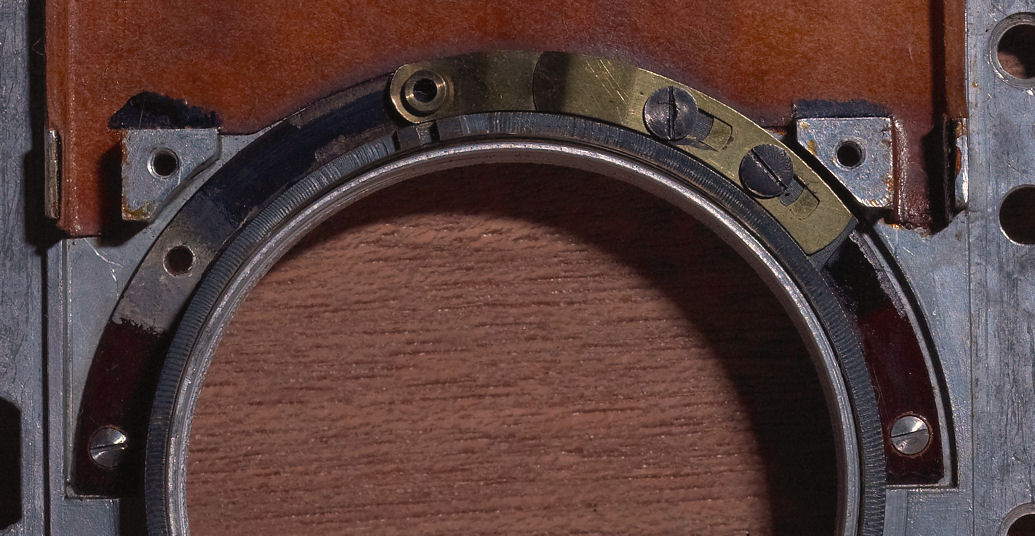
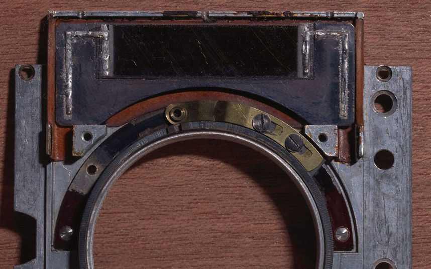
This set of two pictures illustrate the main design fault with the Contaflex shutter. The picture at the left is a cropped portion of the shutter control mechanism above. You can see in the center of the picture the spring finger that connects with the escapement mechanism to change shutter speeds. The position of this finger moves as the shutter speed range selector is rotated.
This finger fits into the slot in the escapement platform shown in the next picture at the lower left corner. When the shutter speed range selector knob is rotated, the escapement platform is moved up or down on its tilted platform. The escapement platform rotates around a pivot point on the far right. This pivot point is at far right and is covered by a large screw. The metal of the platform is also very thin at the pivot point. The problem with this arrangement is that the surface upon which the escapement platform is mounted is tilted at about a 30 degree angle. The result of the geometry of this arrangement, and the insufficient thickness of the platform at the pivot point is that when the position of the escapement platform is changed, it tends to lift up on the left side, which is where the escapement gears and the shutter gears mate. This lifting causes the gears to mate improperly, resulting in excessive friction. The overall result is a shutter whose slow speeds cannot be controlled properly. It is just barely possible to see that Zeiss machined a slot into the platform at the left. This was clearly intended to mate with a guide which would hold the platform level. But when the camera was manufactured no such guide was installed. As you can see in the picture there is no indication such a guide was ever installed. Obviously, when the metal of the escapement platform was new, it was stiff enough for the shutter to function properly without the guide. However, one is required now, and one has been made and installed in this camera.
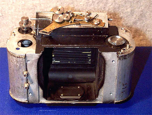
Here is the camera with both haves reattached with all internal mechanisms installed, ready for the front plate assembly and viewfinder. You can see the black plastic cap over the rewind gear on the right of the camera in the front view.
Finally, here is the camera, fully assembled and ready for the leather. Although you can't see it, the camera has been carefully sealed by the application of plastic sealing compound to all the joints, through covering all openings with cemented thin brass strips, and by the use of filling compound. Notice that the flash synchronization contacts have been removed and replaced with aluminum plugs. The flash system was installed by an amateur and could not work. The owner requested the camera be completely restored to the maximum extent possible.
One of the main problems with this camera was that it was literally filled with small particles of disintegrated leather and flakes of deteriorated shellac glue. When this camera was last serviced in 1956 the body was not sealed, and the long term result was the filling of the camera with a great volume of dirt, leather and old glue. It has required many hours of labor to remove all traces of the old glues from inside and outside the camera body.
Although you can't see this in the picture, both the viewing and taking lenses have been serviced. The old oil in the front plate mechanism and the old grease in the taking lens deteriorated and filled the entire lens, covering the optical surfaces with a layer of oxidized oil. In a camera of this age, it is absolutely necessary to have the lenses serviced to obtain the high quality photographs this camera can take. Now that the body and lenses are in like new condition, this camera is almost ready to go. All that is needed is the leather and a final focus check.
Here is it, finished at last, ready for years of taking perfect pictures:
This is a work in progress.
