Zeiss Ikon Contax Camera Repair
A home for your Zeiss Ikon Contax, Contarex or Super Ikonta camera!
Body:
- What Condition is Your Camera In Now?
- What is the Contax?
- Contax Shutter Accuracy in a Camera Today?
- What is Shutter Bounce or Blanking?
- What is the Difference Between a Black Dial and a Color Dial Camera?
- Can a Black Dial Camera be Converted to a Color Dial Camera?
- Can Anything be Done for a Gouged Eyepiece Bezel?
- Why is Zeiss Chrome so Bad?
- Can Anthing be Done for Bad Paint?
- Can I have a Camera Custom Built?
- How Should I Care for My Contax?
- The Illustrated Camera
- Why is Zeiss Chrome so Bad?
Rangefinder:
- The Rangefinder Wheel is Hard to Operate, What is the Cause of This?
- The Focusing Helical Seems to Have a Lot of Clearance, is This Normal?
- Why don't the images in my viewfinder and rangefinder line up right?
- The rangefinder image is badly faded, can it be restored?
- My Pictures are Fuzzy. Is it the Lens or the Rangefinder?
- There is a Defect in the Rangefinder Image, Can this be Corrected?
Shutter:
- Pictures of a Shutter Disassembly
- Pictures of a Shutter Assembly
- Why Does the Color Dial Model Shutter Not Release Sometimes?
- What are Shutter Tapes?
- What is Shutter Capping?
- What is Shutter Bounce?
- My shutter appears bent, what causes this?
- Shutter Cocking and Film Advance
- How do you clear a Jammed Camera?
- Why Does the Self Timer Interfere with 1/1250 Speed?
- How are Shutter speeds set on a IIa or IIIa camera?
Lightmeter:
- The IIIa Lightmeter Explained
- My IIIa LIghtmeter Doesn't Respond to Light At All, Can This be Repaired?
- The Needle on My IIIa LIgtmeter Sticks, Can this be Repaired?
- The Response of My Lightmeter to Light is Intermittent, Can this be Repaired?
- Can the IIIa Lightmeter Photocell be Rejuvinated?
Lenses In General:
- How Should a Lens be Cleaned?
- What Can be Done for a Filter Ring Dent?
- What is an Opton Lens?
- What is a Red "T" Coating?
- What is the difference between a Zeiss Opton and a Carl Zeiss Lens?
- Why are there Bubbles in the lens elements in my lens?
- What is Lens Fungus and What Can be Done About it?
- There is Oil on the Aperture Blades, is this Important?
- Can a Badly Scratched Front Element Surface be Repolished?
- What is Lens Element Separation or Cement Failure and What Can be Done about it?
- Can Nikon Lenses for the Nikon Rangefinder Cameras be Used on Contax Cameras?
- Can Jupiter Lenses for the Russian Rangefinder Cameras be Used on Contax Cameras?
- The 85mm f4.0 Sonnar
Leather:
- Where Can A New Camera Case Be Found?
- What are Zeiss Bumps?
- Can Zeiss Bumps Be Removed?
- Can Damaged Original Leather Be Replaced?
- "Zeiss Bump" Removal from Leather
Emergency:
Overhauling A Contax IIA/IIIA - Light Meter
The IIIa Light Meter
The Contax IIIa light meter is a deceptively complex and extremely delicate mechanism. While all other mechanisms in the camera can take an occasional shock, the IIIa light meter can easily be damaged by an incautious tossing of the camera onto a car seat.
The main problem with the Contax IIIa light meter is the advanced old age of its selenium photocell. The photocell generates a small electrical current when it is exposed to light. It is this electrical current that causes the meter needle to deflect and provide a light reading. The cells in most Contax IIIa cameras are at least 45 years old and have aged to the point of uselessness. The Contax IIIa light meter can be extremely responsive and accurate provided it has a fresh photocell in it. Replacement photocells of a quality high enough for the Contax have only recently become available and I have obtained a supply of them. The following picture is of a typical original Contax IIIa light meter photocell:
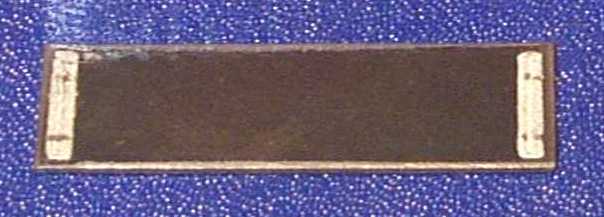
You can clearly see the positive electrical contact pads at the right and left. The back of the cell serves as the negative terminal. The black material covering the cell is the element selenium. The electrical contact pads sit on top of the layer of selenium. What you cannot see is a transparent layer of metal that has been evaporated in a vacuum, in the same manner as lenses are coated, on top of the selenium layer. This transparent layer of metal collects the electricity from the microscopic crystals of selenium and transmits it to the conducting pads at the right and left of the cell surface. It is the oxidation and deterioration of this microscopically thin layer of evaporated metal that is the cause of the deterioration of the photocell with age. There is no cure for this other than cell replacement.
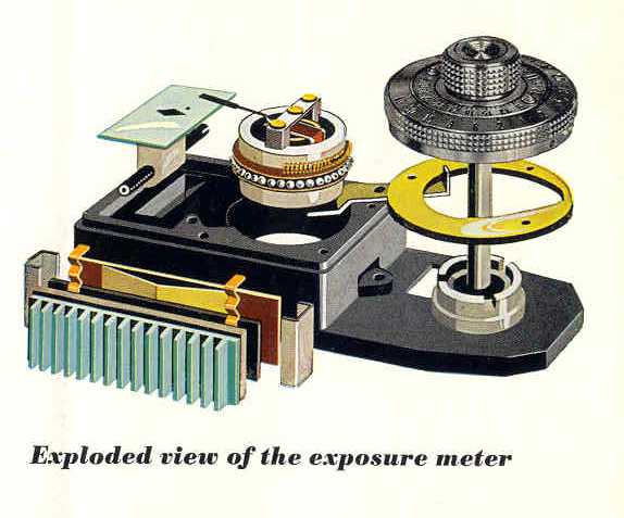
This exploded view of the IIIa light meter provides a clear understanding of how it works. The electrical meter rests in a ball bearing cage. The electrical meter itself is moved by rotation of the adjustment knob through the action of a cammed lever. So there are two movements going on at the same time. The first is the movement of the electrical meter needle in response to the electrical current generated by the action of light on the selenium photocell. The second is the movement of the electrical meter itself in response to rotation of the adjustment knob.
The electrical contact between the cells and the meter can be a source of intermittent or inaccurate operation. There are basically two models of IIIa lightmeters. The first model, has small friction clips that electrically attach the cell to the meter. Over time dirt, oil and corrosion can reduce or interrupt the electrical connection. Zeiss recognized this problem very late in Contax IIIa production and changed to all soldered connections. In these meters there are small wires which are soldered to the cell and then into the meter. These soldered connection meters are completely reliable and have almost no cell connection type problems. It has become apparent to me that the soldered conneciton method is the only way to connect new cells reliably to a meter and so it is is my practice, as of January 2007, to modify all Contax IIIa light meters with friction type contact systems so that they are changed to soldered type connections. There is a reasonable fee for this service and this is explained further in the price list.
Occasionally I will come across a IIIa with a lightmeter that has been worked on by an amateur. The innermost workings of the electrical meter are so delicate it requires the skills and perceptions of a trained watchmaker to be able to work on one without the possibility of irreparable damage occuring. In many cases where an amateur worker has opened the meter covering I have found the meter to be irreparably damaged. Unfortunately, it is not possible to determine if a meter is permanently damged from an external examination of the camera. Fortunately replacement meters can be installed to correct this situation.
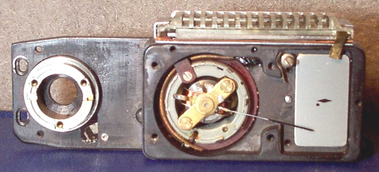
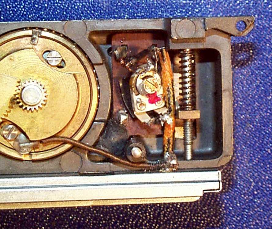
The next picture is of the light meter with the top removed. You can see the long thin indicating needle. This is very sensitive to shock. Many cameras I see require the needle to be very delicately and carefully bent back into normal position. A strong bump or shock to the camera can bend it upward or downward sufficiently so that it will rub and make the meter very inaccurate.
Although hiden beneath the brass "bridge" in the picture below, the indicating needle is attached to a rotating armature that is suspended on two needle point bearings. You can see the bearing mount for the upper bearing in the exact center of the brass "bridge" in the meter below. There is a very fine spring, called a "hairspring" that provides the very delicate tension suspension of the armature so that when the cell voltage increases in response to an increase the the light level, the needle will move upward and then return whent he light level lowers. The hairspring is below the center of the brass bridge and also is the electrical connection between the photocell and very fine copper wire coil in the rotating armature. The hairspring has great strength when the armature is moved in a direction that coils it tighter, but it can be permanently bent if the rotating armature is rotated backward.
Please take careful notice of the long small copper coil spring that surrounds the left half of the outer circumference of the meter mechanism. This coil spring is the key to how the meter is adjusted by the meter adjustment knob. When the adjustment knob is rotated a mechanical lever causes a gear train to rotate the outer part of the electrical meter to bring the needle into alignment with the diamond mark on the meter face. So there are two moving parts in the electrical meter. In inner rotating armature and the external rotating magnet. The internal armature rotates and moves the needle in response to light, and the external magnet moves in response to changes in the adjustment knob position. It is the outermost copper coil spring that tensions the adjustment mechanism. The brass bridge is connected to the magnet by the little bolts at each end, so the magnet and the rotating armature are mechanically connected through the hairspring. And it is this connection that is the key to understanding just how easily the IIIa lightmeter can be destroyed.
You can also see at the upper right the small gold plated brass connection of the friction type cell connector.
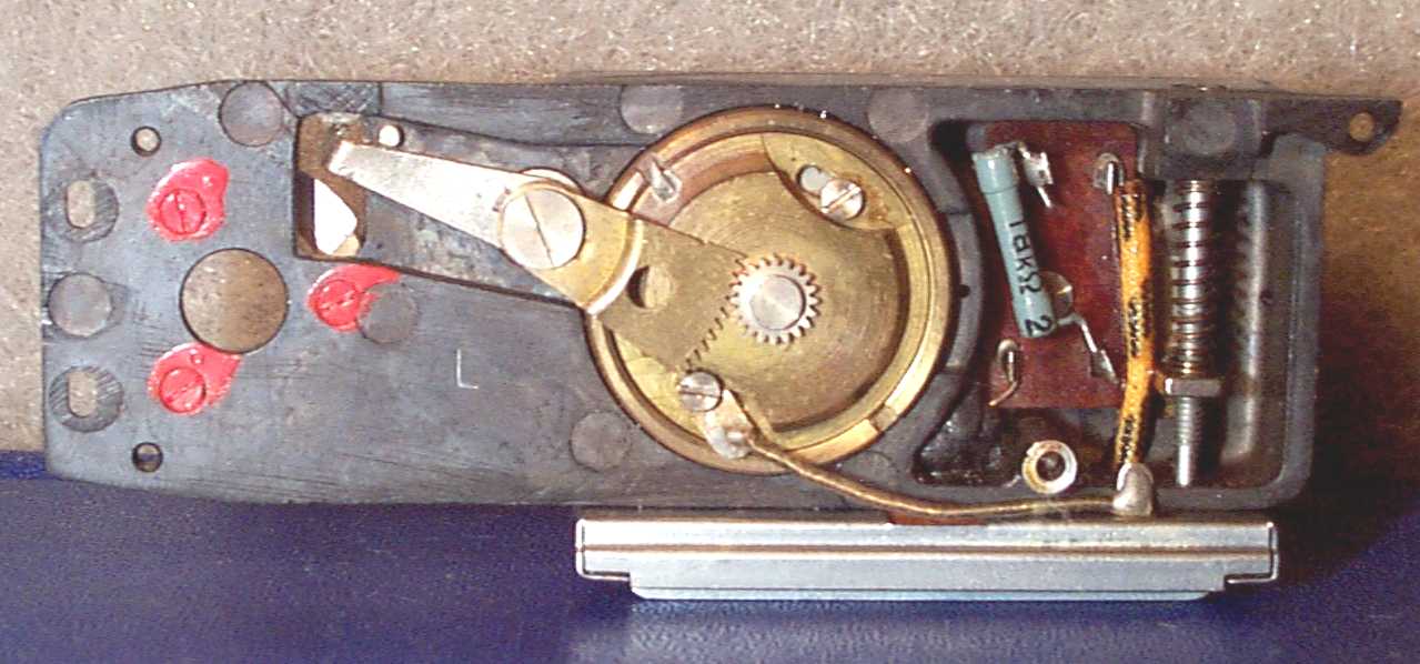
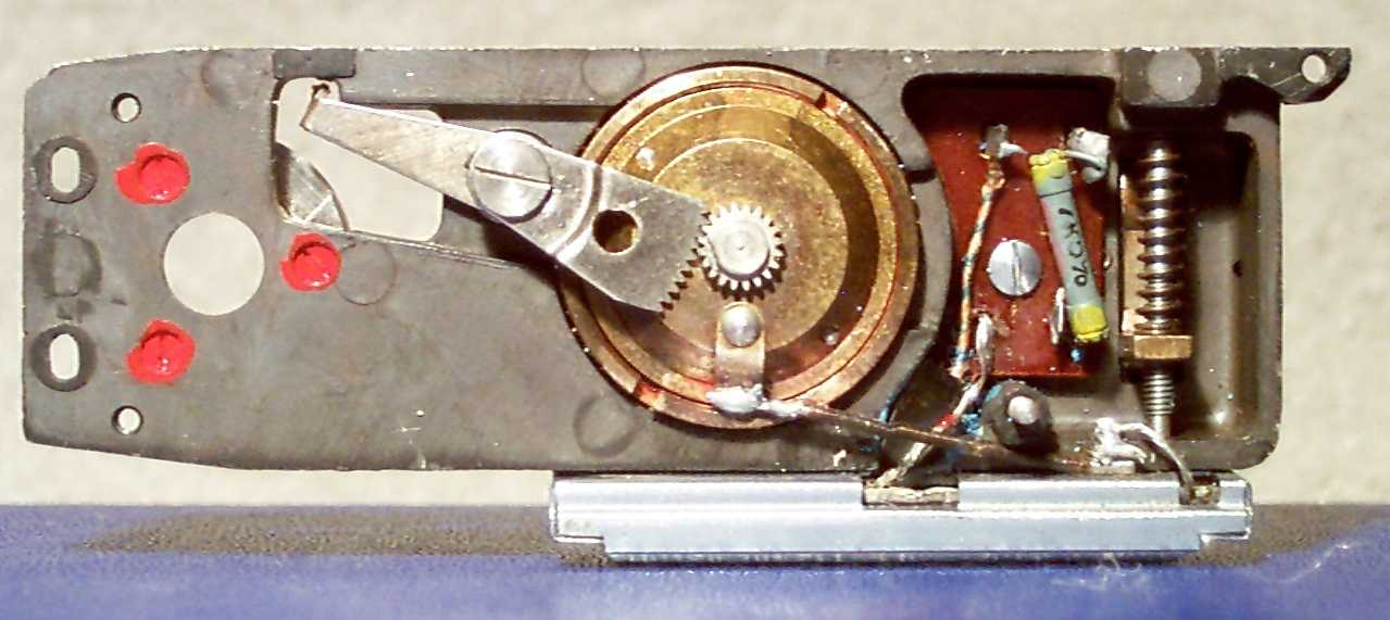
This is a picture of the underside of the type 1 IIIa light meter module. You can see the adjusment screw on the upper right of the of the brass barrel of the lower meter housing. Note also that the cell connection is with a screw. These, in addition to the manner of cell connection, distinguish the type 1 meter from the type
You can clearly see how the lever rotates the magnet through a gear connection. As the adjustment knob is turned, the lever shifts position and this causes the gear to rotate the magnet. The meter hairspring will be excessively uncoiled so that it is permanently snarled and the meter is destroyed if the lever is removed and the brass barrel in the picture below is allowed to rotate backwards.
The brass barrel rotates over a set of 24 small steel ball bearings. Notice that the photcell is electrically connected to the brass barrel through a very fine copper spring. The electrical connectoin between the brass barrel and the upper meter electrical mechanism is the bearing balls. When these become coated with deteriorated grease and oil from the adjusting knob mechanism the electrical connection can be broken, become intermittent, or have increased electrical resistance resulting in meter inaccuracy.
Please notice that the brass barrel in the Type I meter has two steel screws at the top and bottom. These allow for the position of the magnet to be adjusted without removal of the lever. I find fewer destroyed Type I meters than I do Type II meters. There is a good reason for this.
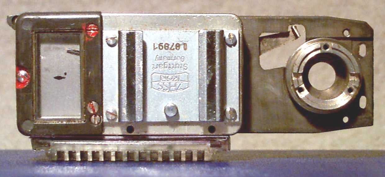
This is a picture of the underside of the type 2 IIIa light meter module. The Type 2 module is distinguished by the riveted cell connection at the lower brass barrel of the lower meter housing and soldered cell connections.
Please notice the absence of the adjustment locking screws. The only way to adjust the Type II meter to a new cell is to remove the lever and set the brass barrel to a new resting positon. This is a very dangerous thing to do since removal of the lever without a tight control over the barrel will cause the barrel to over rotate backwards under the tension of the internal copper coil spring resulting in permanent damage to the hairspring and destruction of the meter.
Zeiss recognized this problem, and the last set of III cameras manufactured in 1963 contained a variable electrical resistor on the circuit board which allows the meter to be accurately set without removal of the lever. It is my practice to install this variable resistor in every meter that is overhauled here. This modification is included in the cost of a light meter overhaul. This picture shows this resistor:
This meter was defective from the factory and had never functioned properly. The defect was an electrical short between the meter cell connection and the meter module body. This short was located beneath insulating paint and was difficult to find.
Here is a top view of the same meter. You can see how the adjusting lever is positioned to fit into the cam underneath the adjusting knob.
IIIa Lightmeter Doesn't Respond to Light?
A large number of IIIa light meters no longer respond to light at all. In more than 90% of these cases, the problem is a completely dead old photocell. Even if the meter responds to light, if it has its original photocell it is most likely not responsive enough to provide meter accuracy. Most old cells I see are at least 2.0 f stops inaccurate. I have in stock brand new photocells. These new photocells incorporate the latest technology in selenium light sensing cells and have a longer life, are more responsive, respond to changing light levels faster, have a more linear output, and are an exact replacement for the original cells in fit and finish. In most cases, all that is required to bring your light meter back to better than like new performance is a servicing and the installation of a new photocell.
If your meter has mechanical or electrical problems that can be corrected without the need for replacement parts, this work is done without additional cost. All work necessary to return the meter to better than original accuracy is included in the cost of a new photocell. This includes cleaning, lubrication, and precision adjustment using a Honeywell precision light source and a Spectron Camera Tester.
Some light meter designs used in early camera production by Zeiss have electrical connection problems caused by friction type electrical connectors. It is now my practice to modify these type meters to have soldered connections. This is the only way to ensure complete reliability. The point is to provide you with an accurate, responsive and completely reliable light meter on your IIIa camera.
Less than 1% of meters have been damged beyond repair. Usually this has happened by the meter being opened by unqualified persons. But even if the meter internals have been severely damaged, in most cases satisfactory repairs can be made. Regardless of the amount of work required to repair your meter, it is all covered by the one time fee for replacement of the cell.
If your lightmeter should be damaged beyond repair I have reasonably priced replacement meters available in stock so your camera can always be returned to better than like-new performance.
IIIa Light Meter Needle Stickiness?
It is very common for people to make the observation that the needle on a IIIa light meter to stick on the bottom and require a light tap in order for it to respond to light. This behavior is actually not a problem at all, and it is easily eliminated.
The natural inclination is to operate the light meter with the adjustment knob kept rotated fully clockwise when the meter is not in use and the cap is closed over the photocell. The proper way is to keep the adjustment knob kept in the fully counter clockwise position. When this is done, and the photocell cap is opened, the needle will immediately move to the top of the range and it will not stick. Then, the adjustment knob is rotated clockwise to bring the needle to match with the point on the diamond.
When the adjustment knob is kept in the fully counter clockwise position the needle will indicate on the dot just below the diamond if it is adjusted properly when the photocell cap is closed. When the needle is on the dot it tells you the mechanical parts of the meter are adjusted properly. So keeping the adjustment knob in the fully counter clockwise position always gives you a check on your meter condition.
The reason the needle sticks when the dial is kept in the clockwise position is simple. When this is done the indicating needle is held tightly against the bottom stop. This cocks the armature, to which the needle is attached, in its bearings. When the adjustment knob is moved it takes a relatively large amount of rotation or a slight tap on the meter to free the needle bearings so that the armature can freely rotate and the needle can indicate.
So keep your adjustment knob rotated fully counter clockwise and everthing will indicate smoothly and properly.
Can Light Meter Intermittent Operation be Corrected?
Zeiss made a lot of changes to the light meters during the years they were produced. For the most part these changes were made to the parts that make the electrical connection to the photocell. In the first models Zeiss used friction contacts made of copper to make the connections to the contacts on the front of the photocell, and a nickel plated contact to make the electrical connection to the back of the cell.. But the copper surface quickly corroded and this caused intermittent connection problems. Then the copper parts were gold plated, but then the nickel parts would corrode after a longer time and this would cause intermittent connection problems. Finally Zeiss used all soldered connections. This solved the intermittent connection problems. Most of the light meters that were produced have mechanical friction type connections.
If your light meter is having intermittent operation problems these can be solved by having your meter modified to be like the last production type meters with soldered cell connections. All Contax IIIa light meters with friction connections that are overhauled here are modified to have soldered connections.
If your light meter is having intermittent operation problems and you want this problem solved permanently, write to me.
Can the IIIa Light Meter Photocell be Rejuvenated?
The photocell provides the electrical current in response to light that makes the light meter needle move. The Contax IIIa light meter photocell is a thin metal sheet that is coated with the element Selenium. Selenium gives off electrons when it is exposed to light. The electrical connections to the photocell are made by making one electrical connection to the back of the photocell. An electrical connection to the back is easy because it is made of steel coated with a layer of silver. The connection to the front is much more sophisticated, and this is the reason photocells age and die. The front surface of the selenium layer is coated with a transparent layer of conducting metal, usually silver. This layer is applied in a vacuum where tiny amounts of silver are vaporized which then condenses on the surface of the photocell. This coating is in the same manner whereby anti reflection coatings are applied to lenses. Over time the thin layer of metal is attacked by oxygen in the air, and slowly with time it becomes less and less electrically conductive. This process of deterioration takes many years. But it is the reason that by now most, if not all, photocells installed in IIIa light meters are at the very end of their lives. It is not possible to rejuvenate a photocell by applying a new coating since this would only apply a good coating over a bad one. The best thing to do is to replace the photocell.
The Contax IIIa meter is highly sensitive and accurate. With a new photocell installed it is fully capable of supporting the use of films with the most narrow exposure latitudes such as Kodachrome or other reversal color films.
