Zeiss Ikon Contax Camera Repair
A home for your Zeiss Ikon Contax, Contarex or Super Ikonta camera!
Body:
- What Condition is Your Camera In Now?
- What is the Contax?
- Contax Shutter Accuracy in a Camera Today?
- What is Shutter Bounce or Blanking?
- What is the Difference Between a Black Dial and a Color Dial Camera?
- Can a Black Dial Camera be Converted to a Color Dial Camera?
- Can Anything be Done for a Gouged Eyepiece Bezel?
- Why is Zeiss Chrome so Bad?
- Can Anthing be Done for Bad Paint?
- Can I have a Camera Custom Built?
- How Should I Care for My Contax?
- The Illustrated Camera
- Why is Zeiss Chrome so Bad?
Rangefinder:
- The Rangefinder Wheel is Hard to Operate, What is the Cause of This?
- The Focusing Helical Seems to Have a Lot of Clearance, is This Normal?
- Why don't the images in my viewfinder and rangefinder line up right?
- The rangefinder image is badly faded, can it be restored?
- My Pictures are Fuzzy. Is it the Lens or the Rangefinder?
- There is a Defect in the Rangefinder Image, Can this be Corrected?
Shutter:
- Pictures of a Shutter Disassembly
- Pictures of a Shutter Assembly
- Why Does the Color Dial Model Shutter Not Release Sometimes?
- What are Shutter Tapes?
- What is Shutter Capping?
- What is Shutter Bounce?
- My shutter appears bent, what causes this?
- Shutter Cocking and Film Advance
- How do you clear a Jammed Camera?
- Why Does the Self Timer Interfere with 1/1250 Speed?
- How are Shutter speeds set on a IIa or IIIa camera?
Lightmeter:
- The IIIa Lightmeter Explained
- My IIIa LIghtmeter Doesn't Respond to Light At All, Can This be Repaired?
- The Needle on My IIIa LIgtmeter Sticks, Can this be Repaired?
- The Response of My Lightmeter to Light is Intermittent, Can this be Repaired?
- Can the IIIa Lightmeter Photocell be Rejuvinated?
Lenses In General:
- How Should a Lens be Cleaned?
- What Can be Done for a Filter Ring Dent?
- What is an Opton Lens?
- What is a Red "T" Coating?
- What is the difference between a Zeiss Opton and a Carl Zeiss Lens?
- Why are there Bubbles in the lens elements in my lens?
- What is Lens Fungus and What Can be Done About it?
- There is Oil on the Aperture Blades, is this Important?
- Can a Badly Scratched Front Element Surface be Repolished?
- What is Lens Element Separation or Cement Failure and What Can be Done about it?
- Can Nikon Lenses for the Nikon Rangefinder Cameras be Used on Contax Cameras?
- Can Jupiter Lenses for the Russian Rangefinder Cameras be Used on Contax Cameras?
- The 85mm f4.0 Sonnar
Leather:
- Where Can A New Camera Case Be Found?
- What are Zeiss Bumps?
- Can Zeiss Bumps Be Removed?
- Can Damaged Original Leather Be Replaced?
- "Zeiss Bump" Removal from Leather
Emergency:
Overhauling A Contax IIA/IIIA Body - Rangefinder
When Was A Particular Camera Made
This is a fairly common question and one that is very difficult to answer. The reason for this is that the way Zeiss handled cameras returned to the factory because they were defective was to simply take them apart, remanufacture them, and then return them to the market as new cameras. So it is possible for a camera to have been made several times. Many Contaxes were made in the Zeiss Official Camera Repair centers out of spare parts. This was done during the time Contaxes were being made and then after official production stopped. Also, Contaxes and FrankenContaxes have been made by unscrupulous workers for many years. The serial numbers really aren't all that reliable. What matters most is if the camera is made out of the last design parts? Over the time of production Zeiss made changes to the shutter speed controller, the light meter, and the rangefinder. It is better to have a camera with a 1951 serial number but which contains 1970 parts than it is to have one with a 1970 serial number and 1951 parts.
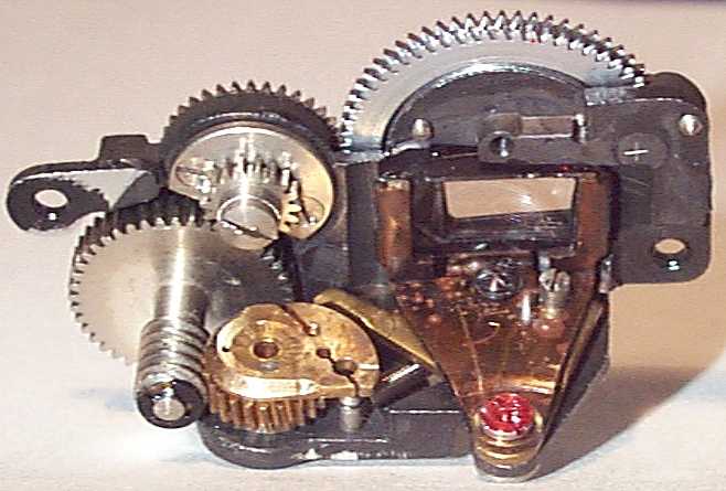
It was regular practice to substitute new parts for older ones when a camera was presented for service due to design improvements. A good example of this is the tiny speed controller that controls the shutter speeds from 1 sec. to 1/50 sec. The following pictures demonstrate this.
This is a picture of the first design of speed controller that came with the very first Contax IIa's sold in 1951:
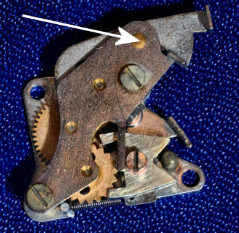
The white arrow points to the bearing of the main controller arm. This arm holds back the shutter from closing for a predetermined time. This first design suffers from a primitive arm bearing and the arm itself has no separate return spring. It was very unreliable and was quickly replaced with the second design. Most of these were changed out and I've only seen one camera come here with this type of speed controller in it. My best guess is this controller was improved within months of cameras being sold with it. This is because it was just too crude to work reliably.
This is a picture of the second speed controller design:
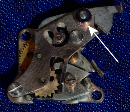
The white arrow points to the improved bearing assembly. You can see it is now made up of a high precison steel shaft in a brass bearing. But it still has not got a separate return spring. This design makes up about 10% of the cameras that come here.
This is a picture of the third speed controller design:
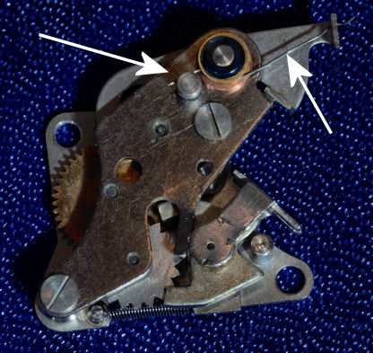
The white arrows show the holding post and the control arm return spring. This improvement made the controller to be completely reliable and there were no further improvements.
When a camera comes here with a design 2 type controller part of the overhaul process is to manufacture and install a custom made control arm return spring so that it's essentially converted to a design type 3:
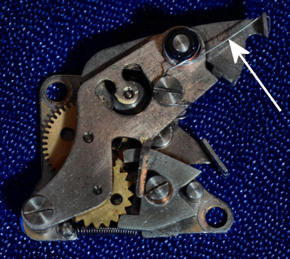
The white arrow shows the newly installed return spring. Notice there's no resting post and so the spring has to have a different design, but it works just as well as if it was factory made.
The Focusing Wheel is Hard to Operate
It is part of the normal camera aging process for the focusing wheel to become progressively harder to operate until finally it becomes painful to the finger. it is also possible that when the camera was originally assembled it was put together with a very stiff and rough focusing action.
There are six possible causes for hard, rough and noisy focusing action:
- The first is dirt and environmental grime build up in the focusing helical threads in the lens mount.
- The second is oxidation of the surface of the brass focusing helical threads in the lens mount assembly.
- The third is the build up of fine dust in the helical threads.
- The fourth is the drying of lubrication in the range finder assembly. A more infrequent cause is the drying out of lubricating grease improperly applied to the focusing helical threads by the original camera assembler or by a subsequent worker.
- The fifth is that it is also possible for a very slight misalignment of the lens mount assembly when it is attached to the camera body to cause binding. This can also happen if the camera has been dropped. Frequently when a Contax has been dropped on the lens there will be no obvious damage to the lens mount assembly, but it will be distorted by the impact.
- The Sixth is that it is possible for the surface finish and inner diameter of the stationary part of the focusing assembly to so match with the surface finish and inner diameter of the moving part of the focusing assembly so that they tend to catch against each other when rotation occurs. This possibility is the consequence of the use of an Acme type thread profile in the focusing assembly helical threads. Most, if not all, cameras ever made use the Acme type thread design in focusing assembly helical threads. The reason for this is that the Acme thread type design is very resistant to fouling by dirt and wear products. But it does require great precision in surface finish and component manufacture to avoid a thing called "juddering", which is what happens when moving parts catch and then move as they are rotated against each other. In some cameras the focusing assembly components were unfortunately mismatched with they were assembled.
The proper alignment of the focusing assembly to the camera body is highly critical to smooth and precise focusing action and feel. It can sometimes be extremely difficult to get this alignment just right because some cameras require a precision of one ten thousandth (0.0001"). The skirt of the focusing assembly mounts to the camera with five evenly spaced screws. Extremely thin spacing washers are placed beneath the skirt between it and the camera body at each screw. I have overhauled cameras that required no less than five sold hours of work to obtain a proper alignment of the focusing assembly to the body.
Fortunately is is possible in all cases to restore the focusing mechanism operating friction to better than when it was new. This is accomplished by careful ultrasonic cleaning of all the components, followed by the proper lubrication, and extreme care in the alignment of all the components when the camera is assembled. A distorted lens mount assembly can usually be restored to free rotation through the use of a great amount of elbow grease, fine diamond lapping compound and very thin spacing washers.
Zeiss was aware of the friction problem with the Contax focusing mechanism. I recently came across a Contax IIa with an experimental lens mount assembly in it. The focusing assembly had been made so the threads at the rear of the mount could be made to have a tighter fit than the threads at the front. This was done by the making of four equally spaced slits down the length of the helical. A groove was then cut around the rear circumference of the lens mount with a fine steel wire wrapped tightly in the groove to pull in the rear of the threaded section of the focusing assembly somewhat like a collet. The reason for this experiment was to obtain a looser fit at the front of the mechanism that would lower the friction combined with a tighter fit at a smaller portion at the back to increase the focusing precision lost by the looser thread fit. It didn't work from the factory. but I made it work through the use of much elbow grease and diamond lapping compound to lap the threads together to precisely the proper tolerance. It took about a day of very hard work to get it just right which explains why it was only experimental and was never implemented in regular production.
I can duplicate this in your camera if you would like to have absolutely spot on precision focusing action, but it will definitely not be cheap.
There is a very close connection between the tightness of fit of the focusing helical threads, the friction it takes to rotate the lens mount, and the degree of focusing precision that is possible. The looser the thread fit, the easier it is to operate the focusing wheel, the less precise the focusing. The average precision of focusing with a typical Contax is about four inches due to focusing helical thread tolerance.
It is part of the normal camera servicing procedure to use very fine diamond compound to polish the helical threads. The result is better than new focusing action. The extreme fineness of the compound I use does not increase the degree of focusing imprecision that is inherent in the mechanism.
No camera leaves here until its focusing action has the same feel as every other camera that leaves here and this is what I expect would be the standard of perfection at the Zeiss factory when the camera was originally manufactured.
What is the Cause of Focusing Helical Clearance or Looseness?
I frequently am asked why the focusing action on a pre-war Contax II or III is much smoother than that of a post war IIa or IIIa camera. The reason this is so is both simple and complex.
It is a fundamental law of camera design that long camera life comes from mating brass moving parts against steel parts wherever possible. Brass against steel wears better than brass against brass or steel against steel.
In the prewar Contax II and III cameras the focus system gear train from the range finder wheel to the rotating focusing helical is brass, steel, brass. And this works very well because the gears are all mounted to the camera body and can be mounted with great precision and firmness. This means that everything can be made so that wear to the moving part of the focusing helical is held to an absolute minimum. So the focusing action is very precise, tight and smooth.
In the postwar Contax IIa and IIIa cameras the focus system gear train is all contained in the range finder module. The range finder module is movable and must be adjusted when the camera is assembled. It is necessary to remove the range finder module to disassemble the camera for maintenance. The result is that it cannot be adjusted to the same degree of precision as the mechanism in the pre war cameras could. This inability to precisely adjust the gearing resulted in the possibility of accelerated wear to the gear teeth that are cut on the moving part of the focusing helical. Zeiss solved this problem by applying a "hard" chrome plate to the gear cuts in the rotating part of the focusing helical. The thick layer of chrome protects the underlying brass from accelerated wear caused by misalignment of the range finder module and its steel gear that rotates the focusing helical..
"Hard" is a technical term applied to chrome plating. It refers to chrome that is plated to a thickness where it is not transparent as it is in normal "decorative" chrome plating. Hard chrome plating is very expensive and very difficult to apply with precision to a complex surface like a focusing helical. It would not have been specified by Zeiss unless it was absolutely necessary. But hard chrome plating introduces a big friction problem.
When chrome is plated thickly (hard) it cracks and develops a microscopically rough surface. So hard chrome is not smooth like decorative chrome. This surface roughness increased the friction of the mating parts of the focusing helical and the only way to decrease the friction and keep the chrome plating was to increase the tolerance of the fit. Rather than do away with the chrome Zeiss decided to increase the clearance between the moving and stationary parts of the focusing helical which made them looser. But even though the clearance was increased the roughness of the chrome plated surface remains.
The good thing about hard chrome is that the microscopic cracks allow it to hold lubricant very well. So parts in valuable machines that must have a long service life, such as locomotives and nuclear submarine parts, are hard chrome plated. The problem with using most grease type lubricants on the Zeiss Contax focusing helical is that they do not decrease the operating friction because the surface area is so large. Most, if not all, lubricants provided by suppliers for photographic use actually make focusing harder when they are used in the Contax II and and IIIa focusing helicals. Oil cannot be used because it will not stay on the helicals and will quickly migrate into the rangefinder system and fog the viewfinder.
Fortunately, there is a solution to this problem. I have recently found a French watch grease that is so finely made and so light it will actually decrease the operating friction of the focusing helical. This grease provides a focusing action that is very smooth and fine, without excessive looseness, and very close to the feel of the pre war Contaxes.
Why don't the images in my viewfinder line up properly?
It is a very common defect for a Contax IIa or IIIa camera to have a problem with the rangefinder where the viewfinder and rangefinder images have a vertical misalignment. In some cases this misalignment is so great it is impossible to focus the camera. This problem has been another reason for there being so many beautiful unused Contaxes for sale.
Zeiss used two different cements to hold the rangefinder module lenses in their frames. The first cement they used is a water soluble glue. This glue appears to me to be hide glue. It deteriorates over time and becomes very brittle. It cracks and crumbles into small pieces. This process leaves the lenses loose in their frames and the shifting of the lenses causes the image vertical offset. I see many cameras where modern plastic cement has been applied to this glue in an attempt to hold it together. This technique works for only a limited time.
The second cement is a black epoxy paste. This was used in later production cameras. This cement is very hard and permanent and holds the lenses tightly in place. Rangefinders in which Zeiss used this cement typically do not have image offset problems and will never develop them.
When a camera is sent here that has the water soluble glue I change it out with modern epoxy. This guarantees the rangefinder image alignment will be permanently correct.
There can be other causes for this problem. Sometimes when the lens cement problem is corrected one of these other problems becomes evident. You can see in the following picture a back view of the rangefinder module that shows the moving lens on the right. The misalignment of the viewfinder image to the rangefinder image can have three possible causes.
1. The small lenses can have been improperly ground, This will usually cause the viewfinder image to tilt slightly from right to left, but still line up properly when the image of concern is in proper focus. It is not possible to correct this defect by adjusting the position of the lenses because they are curved and fit together so closely. They can't be twisted relative to each other. The only solution is to replace the rangefinder lenses and this is always an expensive thing to do. This problem is usually not a large one because the rangefinder functions properly with regard to focus.
2. One or both lenses can have been cemented into their frame(s) upside down, or one or both lenses can be vertically and/or horizontally misplaced in their frames. When this happens there is usually a very visible height difference between the stationary and moving image. It is always possible to correct this problem by removing the lenses and then recementing them in place. However, in some cases the problem of item No. 1 above or No. 3 below will become evident when this is done.
3. Rangefinder misalignment can also be caused by a problem with the large rangefinder prism. The prism is a two piece unit with a 45 degree joint between the two cemented pieces. This joint was cemented with balsam cement which is temperature sensitive. Sometimes if a camera has been overheated at some time in its life the balsam cement will soften and the prism pieces will shift slightly. When this happens the rangefinder alignment will shift in a manner whereby, in most cases, it cannot be corrected by manipulation of the rangefinder unit lenses. In some cases a rangefinder will have an alignment problem that is a combination of a prism and a rangefinder lens problem. In this case only a partial correction of image alignment can be obtained without replacement of the rangefinder prism.
The alignment must be extremely precise and final adjustment of the lenses can sometimes take a week of cementing, moving a lens slightly, then recementing it. Compounding this is the small size and fragility of the rangefinder module parts.
Can a weak rangefinder image be restored?
The range finder prism is a cemented optical assembly. The cemented prism is split at an angle midway between the viewfinder lens and the viewfinder window. One side of the prism was coated with a very thin layer of gold or platinum before the two halves were cemented together with balsam optical cement. It is this reflecting layer of precious metal that half reflects and allows light to transmit through it. If you camera has a gold mirror in its prism, the viewfinder view appears slightly greenish, and the range finder window appears gold. Light transmitted through gold appears green. If the prism in your camera was coated with platinum both the range finder and the viewfinder images have the same normal color.
The following picture shows two prisms for a Contax IIa/IIIa camera. One is complete, and the other has been separated to show the way the prism is put together.
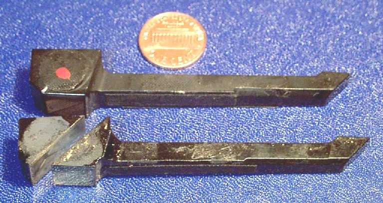
The gold or platinum was deposited onto the surface of the glass through a process called "sputtering". This process deposits a very thin film of metal on a surface that is in a vacuum using high voltage electricity. It is virtually impossible to form the same quality of metal film by methods other than sputtering. Commercial sources are available for this service, but the price is prohibitive. The last quotation I was able to obtain was $450.00 per piece. Clearly, it is cheaper to purchase a parts body merely to obtain the prism from it.
If you have a platinum mirror in your prism, and you have compared the image in your camera to a camera that has a gold mirror in it you may be under the impression there is something wrong with your prism. The key measure of your prism is can you focus easily with it? If you can, and the viewfinder image is not light green, you have a platinum prism and there is nothing wrong with it. The contrast between the range finder and viewfinder images in a platinum prism is much less than exists in a gold coated mirror prism.
The best way to check a prism is to look into it with a magnifier from the front. A good prism will be clean and clear. One that is not good will likely show clearly evident mold growth, mottling and discoloration.
At the time of the writing of this I am experimenting with less expensive methods of restoring the Contax prism. If you have a bad prism and do not want to purchase a parts camera to get a good one, keep checking back. The day I have success this section will be updated.
What Can be Done for Defective Rangefinder Image?
There are a number of defects that can exist in the little rectangular rangefinder image in the viewfinder. They usually show up as black or blocked out portions of the rectangle. These defects can have a great number of causes, all of which will have the same optical result. Among these are chipping or damage to the prism end behind the rangefinder window, damage or chipping to the lenses in the rangefinder assembly, a broken and re cemented prism, paint defects, dirt, or a sticky film chip stuck on the prism end. It isn't possible to know the cause for sure without disassembling the camera.
What Can be Done for a Gouged Eyepiece Bezel?
Zeiss glued the eyepiece bezel into the top plate using a powerful thread locking adhesive. This makes it extremely difficult to remove under the best of conditions. Most workers don't know this and when they try to remove the eyepiece the attempt is made using a pair of pliers. The result is that the jewel like quality of the bezel knurling usually gets gouged and ruined, the chrome gets scraped off in places, and the finely finished annular section around the eyepiece lens picks up a number of very deep and ugly scratches. It's usually a big mess and nothing makes the value of an otherwise beautiful Contax go into free fall harder than a ruined eyepiece bezel.
Luckily a lot can be done to correct the situation. It is possible, using the proper special custom manufactured tools to remove the eyepiece assembly without damaging it further or damaging the top plate paint. Once it is out it is possible to skim cut and then apply new beaded knurling to the outer rim. The inner annulus can also be skim cut to remove scratches and gouges and then refinished to glistening perfection. All this can be followed by Rhodium plating followed by deep coat of diamond hard clear gunsmiths baking lacquer. The result will be like new with only a slight metal tone difference between the original chrome and the new Rhodium plating.
If your problem is a camera that is truly mint otherwise, and nothing but original perfection will do, bright chrome plating is also available at additional cost.
The Cause of Out of Focus Pictures
It is possible for the rangefinder to be the cause of fuzzy pictures, but not usually. My experience has been that the main cause for out of focus pictures is a misalignment of the lens element assembly within its body. The lens is made so that an adjustment for proper focus is relatively easy and straightforward if one has the proper tools and instruments to do it.
It is very easy to check the rangefinder. Check the split image against the engraving on the lens mount on the camera body. If the split image lines up properly on a far object when the lens mount is set at infinity; and then then also at one very nearby the rangefinder is operating properly and the lens is the problem.
