Zeiss Ikon Contax Camera Repair
A home for your Zeiss Ikon Contax, Contarex or Super Ikonta camera!
Body:
- What Condition is Your Camera In Now?
- What is the Contax?
- Contax Shutter Accuracy in a Camera Today?
- What is Shutter Bounce or Blanking?
- What is the Difference Between a Black Dial and a Color Dial Camera?
- Can a Black Dial Camera be Converted to a Color Dial Camera?
- Can Anything be Done for a Gouged Eyepiece Bezel?
- Why is Zeiss Chrome so Bad?
- Can Anthing be Done for Bad Paint?
- Can I have a Camera Custom Built?
- How Should I Care for My Contax?
- The Illustrated Camera
- Why is Zeiss Chrome so Bad?
Rangefinder:
- The Rangefinder Wheel is Hard to Operate, What is the Cause of This?
- The Focusing Helical Seems to Have a Lot of Clearance, is This Normal?
- Why don't the images in my viewfinder and rangefinder line up right?
- The rangefinder image is badly faded, can it be restored?
- My Pictures are Fuzzy. Is it the Lens or the Rangefinder?
- There is a Defect in the Rangefinder Image, Can this be Corrected?
Shutter:
- Pictures of a Shutter Disassembly
- Pictures of a Shutter Assembly
- Why Does the Color Dial Model Shutter Not Release Sometimes?
- What are Shutter Tapes?
- What is Shutter Capping?
- What is Shutter Bounce?
- My shutter appears bent, what causes this?
- Shutter Cocking and Film Advance
- How do you clear a Jammed Camera?
- Why Does the Self Timer Interfere with 1/1250 Speed?
- How are Shutter speeds set on a IIa or IIIa camera?
Lightmeter:
- The IIIa Lightmeter Explained
- My IIIa LIghtmeter Doesn't Respond to Light At All, Can This be Repaired?
- The Needle on My IIIa LIgtmeter Sticks, Can this be Repaired?
- The Response of My Lightmeter to Light is Intermittent, Can this be Repaired?
- Can the IIIa Lightmeter Photocell be Rejuvinated?
Lenses In General:
- How Should a Lens be Cleaned?
- What Can be Done for a Filter Ring Dent?
- What is an Opton Lens?
- What is a Red "T" Coating?
- What is the difference between a Zeiss Opton and a Carl Zeiss Lens?
- Why are there Bubbles in the lens elements in my lens?
- What is Lens Fungus and What Can be Done About it?
- There is Oil on the Aperture Blades, is this Important?
- Can a Badly Scratched Front Element Surface be Repolished?
- What is Lens Element Separation or Cement Failure and What Can be Done about it?
- Can Nikon Lenses for the Nikon Rangefinder Cameras be Used on Contax Cameras?
- Can Jupiter Lenses for the Russian Rangefinder Cameras be Used on Contax Cameras?
- The 85mm f4.0 Sonnar
Leather:
- Where Can A New Camera Case Be Found?
- What are Zeiss Bumps?
- Can Zeiss Bumps Be Removed?
- Can Damaged Original Leather Be Replaced?
- "Zeiss Bump" Removal from Leather
Emergency:
Overhauling A Contax IIA/IIIA - Pictures
The Illustrated Camera:
I have put this page together to demonstrate the various steps in the complete winterization overhaul service of a Contax IIa range finder 35 mm camera. This is a work in progress and so as my overhaul of the current camera progresses I hope to add more pictures to fill out the entire story. The following pictures illustrate parts of the assembly process and pictures of critical cleaning and polishing steps. I am hopeful this first offering will help you understand the workings of this very unusual, complex and high precision mechanical marvel.
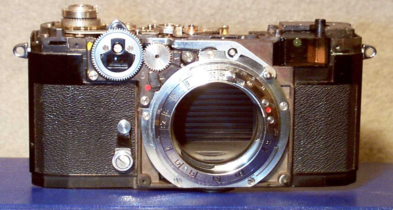
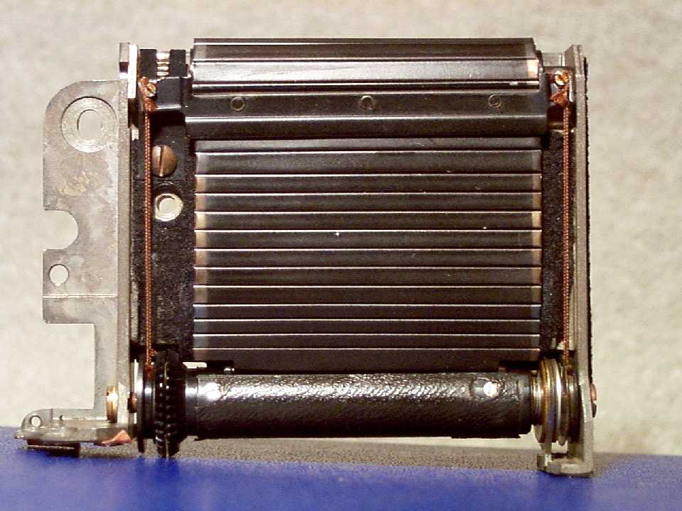
The first picture is of the camera when the top and bottom trim plates have been removed:
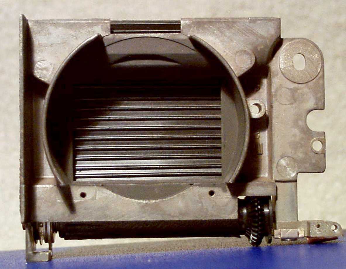
The next picture is of the body shell with the shutter mechanism module removed:
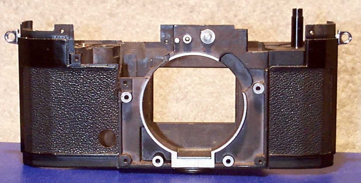
Notice that all components have been removed from the empty shell. This is part of a complete overhaul. All parts must be carefully examined, cleaned and lubricated. This is the only way to take the camera back to the day it was made and get that original factory performance and reliability.
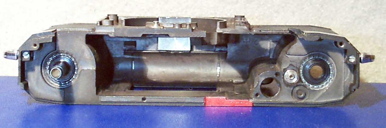
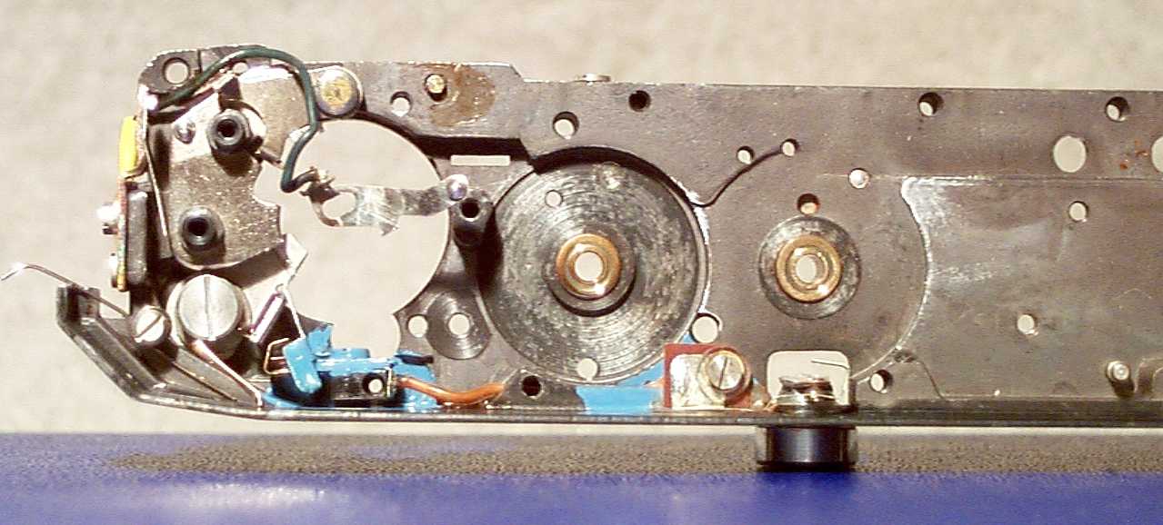
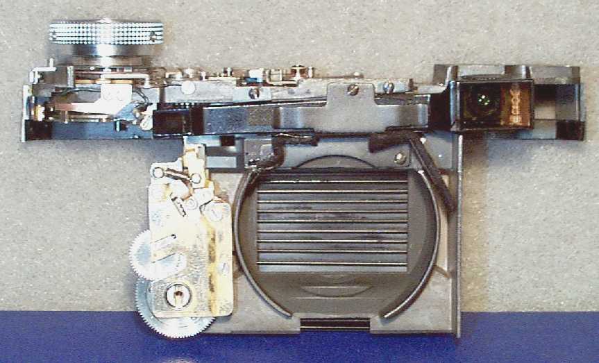
The next picture shows the underside of the shutter module with all the components removed. This view shows clearly the switches and wiring for the flash synchronization system. The blue insulating paint indicates the position of the various switches. One contact is shown loose. This contact is installed when the module is completely assembled. The black cylinder at the bottom center is the PC socket housing.
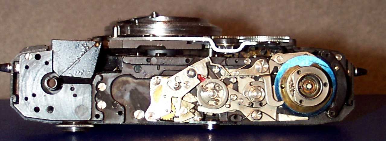
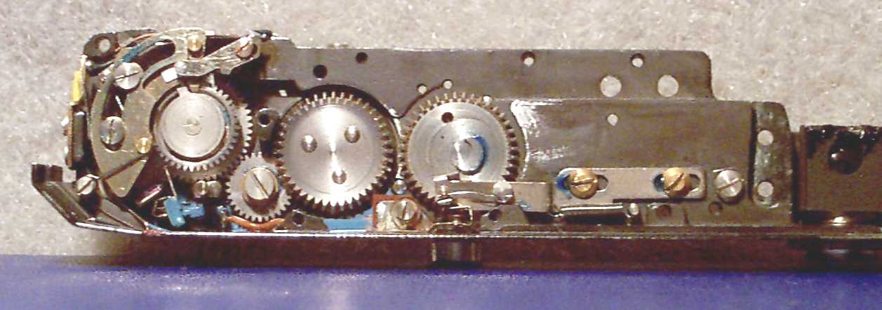
This next picture is the same view of the same assembly, but with all the component parts installed. Note the blue spots of grease. The special low temperature grease has a blue color. When a camera is winterized, grease must be installed in some locations which are not normally lubricated. This is done to prohibit the introduction of condensation during normal operation which can freeze and block mechanism operation in freezing temperatures. The original factory problem with this camera was that the sliding plate that is located at the left in this picture was slightly warped. This warpage kept it from sliding in its curved slot. This plate must move for the shutter to release. Lapping this plate solved the problem.
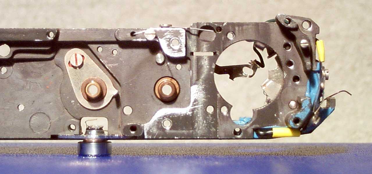
Here is the top side of the same mechanism with all the components removed. Please note the adjustment screw at upper left. This releases the plate directly beneath it to be adjusted. Note the little pin bent up from the plate to the right of the leftmost bearing opening. It is this pin that controls the shutter operation in "B" speed. Wear to the edges of this pin is responsible for a failure of the shutter to hold open when the shutter release is depressed. You can also see the M/X synchronization selector switch at the far right (blue paint). This switch is operated by the shutter speed selector cams automatically.
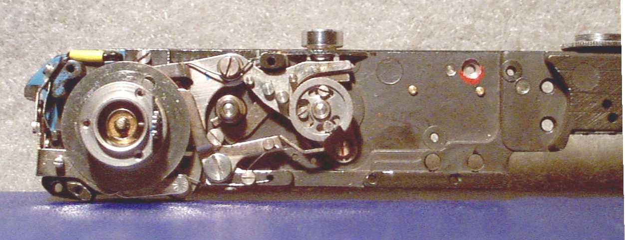
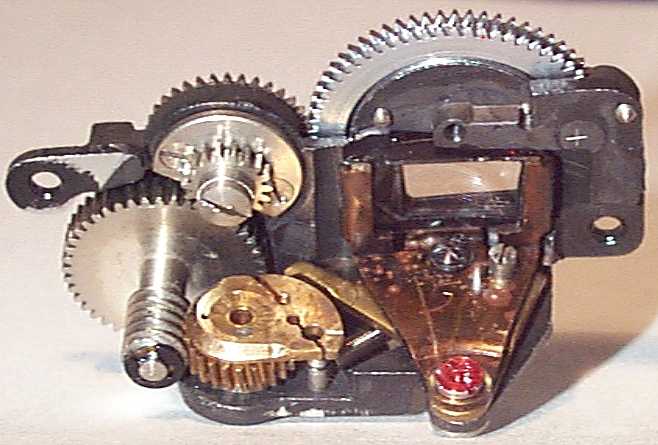
This is a picture of the same assembly, but with most of the parts assembled. The slow speed escapement is not installed. Shutter speed is controlled through a set of two rotating cams. These are located around the film winding shaft. The two cam followers are the shiny steel arms located at the top and bottom of the picture. The shutter release shaft is at the very center of the film wind flange. The film wind flange has three screw holes and is located at the left of the picture.
This is a picture of the shutter module shown as it faces the lens, but upside down from its normal position. The self timer mount is on the right.
This is a view from the rear. The fine cords at the right and left control the lower shutter curtain. In the IIa and IIIa cameras, the upper and lower shutter curtains are separately controlled. This is different from the II and III cameras, where the shutter curtains are controlled together.
This is the completed shutter module. The self timer and viewfinder prism are installed. You can see the viewfinder prism from right to left in the center top of the module. Note that the prism on the IIa and IIIa cameras is not straight, but angles down from right to left. The viewfinder prism is made of two pieces that have been cemented together. Many prisms were slightly misaligned when they were cemented and the result of this is that the secondary image is either slightly higher or lower than the viewfinder image. This is an uncorrectable defect at the present time.
This set of two pictures is of the front and rear view of the range finder module:
In the front view you can see the range finder adjustment ring to the far left and surrounding the range finder front lens. The transfer gear assembly that leads from this ring to the point of mating with the lens mount helical is also shown.
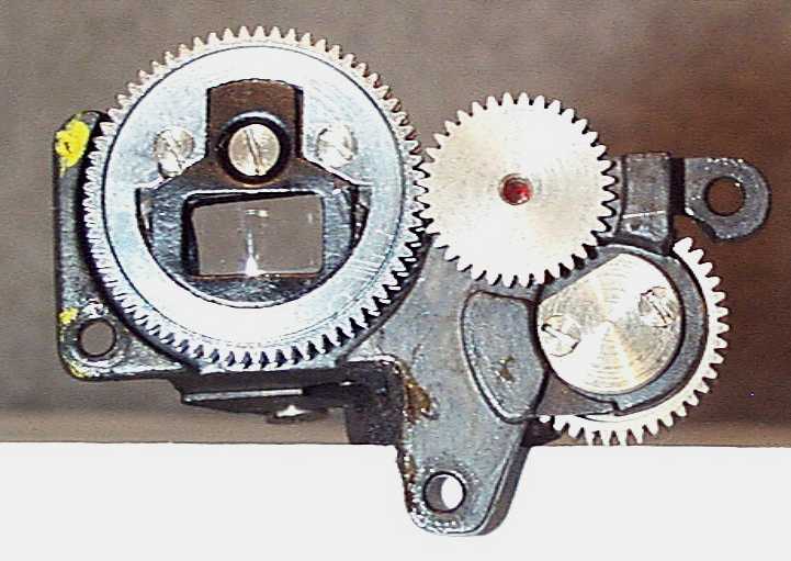
The rear view shows the gear assembly that leads from the adjustment ring to the moving prism lens. You can see the brass gear operated cam and the cam follower from the moving lens assembly. This assembly has been ultrasonically cleaned and so all the metal parts are bright and new.
The next picture is of the range finder assembly mounted on the camera over the prism.

